Suzuki Grand Vitara JB627. Manual — part 374
9B-21 Lighting Systems:
A
A
4
3
B
B
[A]
[B]
A
A
4
B
B
[A]
[B]
11
2
1
7
6
5
12
12
5
10
9
8
10
9
8
7
6
“b”
“a”
“H”
“H”
“H”
“H”
“H”
[F]
[E]
[C]
[D]
A
A
4
B
B
[A]
[B]
“H”
“H”
X
X
X
X
X
X
A
A
4
B
B
[A]
[B]
“H”
“H”
[F]
[E]
[F]
[E]
3
3
3
3
3
3
3
X
X
I5JB0A920022-04
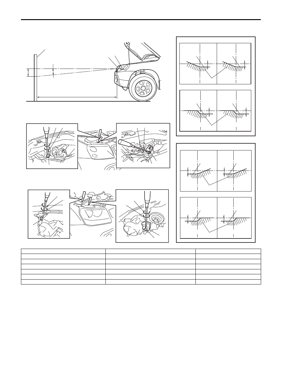
2. Headlight bulb
9. Turning (for right adjustment)
[A]: Left headlight
3. Cut line (bounding line)
10. Turning (for left adjustment)
[B]: Right headlight
4. Hot spot
11. Headlight housing
[C]: RH steering vehicle shown
5. Aiming gear (for up / down adjustment)
12. Headlight leveling actuator
[D]: LH steering vehicle shown
6. Turning (for up adjustment)
X-X: Horizontal center line of headlight bulbs
[E]: 3 door model
7. Turning (for down adjustment)
A-A: Vertical center line of left headlight bulb
[F]: 5 door model
8. Aiming gear (for right / left adjustment)
B-B: Vertical center line of right headlight bulb

Lighting Systems: 9B-22
Headlight Switch (in Lighting Switch) Removal
and Installation
S6JB0B9206006
Removal
1) Disconnect negative cable at battery.
2) Remove steering column hole cover (1).
3) Remove steering column covers (2).
Turn steering wheel to access steering column cover
screws (3).
4) Remove lighting switch (1) from combination switch
assembly (2) and disconnect its coupler (3).
Installation
Reverse removal procedure for installation.
Headlight Switch (in Lighting Switch)
Inspection
S6JB0B9206007
Check for continuity between terminals at each switch
position. If check result is not as specified, replace
switch.
1
2
3
3
I5JB0A940020-02
1
2
3
I4RS0B920005-01
[A]: LHD
[D]: Shaft condition
[B]: RHD
*: If equipped
[C]: Terminal
[C]
[D]
3
5
LOW
PASS
HI
LOW
PASS
HI
LOW
PASS
HI
[A]
[B]
1 6*
2
3
4
5
1 2 3 4
5
1
2
4
6*
I6JB0B920003-02
9B-23 Lighting Systems:
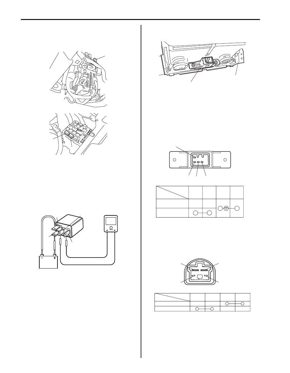
Tail Light Relay, Headlight Relay Inspection
S6JB0B9206030
1) Remove tail light relay (1), headlight low beam relay
(2) and/or headlight high beam relay (3).
2) Check that there is no continuity between terminal
“3” and “4”. If there is continuity, replace relay.
3) Connect battery positive (+) terminal to terminal “2”
of relay and battery negative (–) terminal to terminal
“1” of relay.
4) Check continuity between terminal “3” and “4”. If
there is no continuity when relay is connected to the
battery, replace relay.
Hazard Warning Switch Removal and
Installation
S6JB0B9206008
Removal
1) Disconnect negative (–) cable at battery.
2) Remove audio unit referring to “Audio Unit Removal
and Installation in Section 9C”.
3) Remove center ventilation louver (1) referring to
“Center Ventilation Louver Removal and Installation
in Section 7A”.
4) Disconnect coupler, and then remove hazard
warning switch (2) from center ventilation louver (1).
Installation
Reverse removal procedure for installation.
Hazard Warning Switch Inspection
S6JB0B9206009
Check for continuity between terminals at each switch
position. If check result is not as specified, replace
switch.
Brake Light Switch Inspection
S6JB0B9206010
Check brake light switch for continuity between terminals
at each switch position.
If check result is not as specified, replace switch.
1
2
3
I7JB01920002-01
“4”
“2”
“1”
“3”
I4RS0A920022-01
2
1
I5JB0A920024-01
Switch Position
Terminal
ON
1
2
3
4
OFF
1
2
3
4
I5JB0A920025-01
Terminal
Shaft condition
FREE
PUSH
1
2
3
4
4
2
3
1
I5RS0A920001-01
Lighting Systems: 9B-24
Turn Signal Light Switch (in Lighting Switch)
Removal and Installation
S6JB0B9206011
For removal and Installation, refer to “Headlight Switch
(in Lighting Switch) Removal and Installation”.
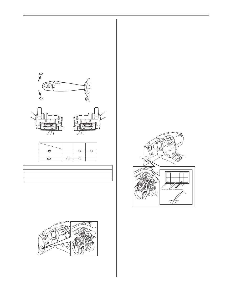
Turn Signal Light Switch (in Lighting Switch)
Inspection
S6JB0B9206012
Check for continuity between terminals at each switch
position. If check result is not as specified, replace
switch.
Turn Signal and Hazard Warning Relay Removal
and Installation
S6JB0B9206013
Removal
1) Disconnect negative (–) cable at battery.
2) Remove turn signal and hazard warning relay (1)
from junction block (2).
Installation
Reverse removal procedure for installation.
Turn Signal and Hazard Warning Relay
Inspection
S6JB0B9206014
1) Remove turn signal and hazard warning relay (1)
from junction block (2).
2) Connect connector to turn signal and hazard
warning relay.
3) Turn ignition switch to ON position.
4) Check turn signal and hazard warning relay for
operation.
• Check that left side turn signal lights flash when 5
terminals of turn signal and hazard warning relay
and vehicle body ground are connected using
service wire (3).
• Check that right side turn signal lights flash when
6 terminals of turn signal and hazard warning
relay and vehicle body ground are connected
using service wire.
• Check that left and side turn signal lights flash
when 8 terminals of turn signal and hazard
warning relay and vehicle body ground are
connected using service wire. If turn signal lights
do not flash, check power supply and ground
circuits of turn signal and hazard warning relay.
[A]: LHD
[B]: RHD
[C]: Terminal
[D]: Switch position
3
1
2
3
2
1
3
2
1
[C]
[D]
[A]
[B]
N
N
I5JB0D920018-01
1
2
I5JB0A920026-01
3
8
7
1
2
6
5
4
2
1
2
3
I5JB0A920027-01
Нет комментариевНе стесняйтесь поделиться с нами вашим ценным мнением.
Текст