Suzuki Grand Vitara JB627. Manual — part 411
10A-10 Cruise Control System:
DTC P0565: Cruise Control On Signal
S6JB0BA104009
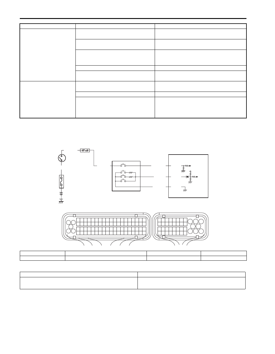
Wiring Diagram
DTC Detecting Condition and Trouble Area
Cruise control cannot be
cancelled
CANCEL switch faulty
Check CANCEL switch for function referring to
“Cruise Control Switch Inspection”.
Brake light switch faulty
Check brake light switch for function referring
to “Brake Light Switch Inspection”.
CPP switch faulty (M/T model)
Check CPP switch for function referring to
“Clutch Pedal Position (CPP) Switch (for
Cruise Control) Inspection and Adjustment”.
Wiring or grounding faulty
Repair.
ECM faulty
Replace after making sure that none of above
parts is faulty.
Cruise control at vehicle
speed stored in memory
cannot be resumed after
cruise control was
cancelled by means other
than MAIN (ON/OFF)
switch
RES/ACC switch faulty
Check RES/ACC switch for function referring
to “Cruise Control Switch Inspection”.
Wiring or grounding faulty
Repair.
ECM faulty
Replace after making sure that none of above
parts is faulty.
Condition
Possible cause
Correction / Reference Item
BLK/YEL
WHT/GRN
2
1
1
3 2
4
5
6
7
8
9
1110
12
13
14
15
16
17
18
19
20
17
18
19
20
21
22
23
24
25
26
27
28
29
30
31
33
34
35
36
37
38
39
40
32
1
2
3
4
5
6
7
8
9
10
11
12
13
14
15
16
21
22
23
24
25
26
27
28
29
30
31
32
33
34
35
36
37
38
39
40
41
42
43
44
45
46
47
48
49
50
51
52
53
54
55
56
57
58
59
60
61
62
63
64
65
66
67
68
69
70
71
72
73
74
75
76
77
78
79
80
81
C37
E23
5V
E23-39
E23-38
BLK/WHT
LT GRN
BLK/YEL
BLU/BLK
3
4
5
6
7
E23-31
I6JB01A10005-01
1. Circuit fuse
3. Cruise control switch assembly
5. RES/ACC switch
7. CANCEL switch
2. ECM
4. MAIN (ON/OFF) switch
6. SET/COAST switch
DTC detecting condition
Trouble area
MAIN (ON/OFF) switch signal voltage is higher than
specified value for 15 seconds continuously
• Cruise control switch and/or its circuit
• ECM
Cruise Control System: 10A-11
DTC Confirmation Procedure
1) With ignition switch turned OFF, connect scan tool to DLC.
2) Turn ON ignition switch and clear DTC.
3) Start engine and warm up to normal operating temperature.
4) Press cruise main switch once.
5) Drive vehicle at 40 km/h (25 mph) or higher for 3 min. or more.
6) Stop vehicle.
7) Check DTC.
DTC Troubleshooting
NOTE
Before this troubleshooting, read and observe “Precautions for DTC Troubleshooting in Section 1A”
Step
Action
Yes
No
1
Cruise control switch check
1) Check cruise control switch referring to “Cruise Control
Is it in good condition?
Go to Step 2.
Replace cruise control
switch.
2
Cruise control MAIN (ON/OFF) switch circuit check
1) Disconnect connectors from ECM with ignition switch
turned OFF.
2) Check for proper connection of cruise control switch
circuit terminal to ECM connector.
3) If connections are OK, check the following for cruise
MAIN (ON/OFF) switch circuit.
Voltage of between “BLK/WHT” wire terminal of cruise
control switch connector and vehicle body ground is 0 V
with ignition switch tuned ON (power short check)
Is it in good condition?
Substitute a known-
good ECM and recheck.
Repair or replace wire
circuit.
10A-12 Cruise Control System:
DTC P0566 / P0567 / P0568: Cruise Control Off Signal / Resume Signal / Set Signal
S6JB0BA104010
Wiring Diagram
Refer to “DTC P0565: Cruise Control On Signal”.
DTC Detecting Condition and Trouble Area
DTC Confirmation Procedure
1) With ignition switch turned OFF, connect scan tool to DLC.
2) Turn ON ignition switch and clear DTC.
3) Start engine and warm up to normal operating temperature.
4) Press cruise main switch once.
5) Drive vehicle at 40 km/h (25 mph) or higher for 3 min. or more.
6) Stop vehicle.
7) Check DTC.
DTC Troubleshooting
NOTE
Before this troubleshooting, read and observe “Precautions for DTC Troubleshooting in Section 1A”.
DTC detecting condition
Trouble area
P0566:
CANCEL switch signal voltage is lower than specified value
for 40 seconds continuously
P0567:
RES/ACC switch signal voltage is specified value for 120
seconds continuously
P0568:
SET/COAST switch signal voltage is specified value for 120
seconds continuously
• Cruise control switch and/or its circuit
• ECM
Step
Action
Yes
No
1
Cruise control switch check
1) Check cruise control switch referring to “Cruise Control
Is it in good condition?
Go to Step 2.
Replace cruise control
switch.
2
Cruise control command switch circuit check
1) Disconnect connectors from ECM with ignition switch
turned OFF.
2) Check for proper connection of cruise control switch
circuit terminal to ECM connector.
3) If connections are OK, check the following for cruise
command switch circuit.
• Resistance between “LT GRN” wire terminal and
“BLK/YEL” wire terminal of cruise control switch
connector are infinity (no continuity check)
• Resistance between “LT GRN” wire terminal of cruise
control switch connector and vehicle body ground is
infinity (ground short check)
Is it in good condition?
Substitute a known-
good ECM and recheck.
Repair or replace wire
circuit.
Cruise Control System: 10A-13
DTC P0571: Brake Switch Circuit
S6JB0BA104011
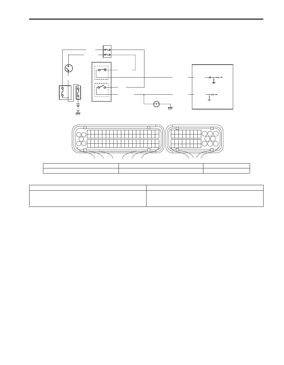
Wiring Diagram
DTC Detecting Condition and Trouble Area
DTC Confirmation Procedure
1) With ignition switch turned OFF, connect scan tool to DLC.
2) Turn ON ignition switch and clear DTC.
3) Start engine and warm up to normal operating temperature.
4) Drive vehicle at 50 km/h (31 mph) or higher for 3 min. or more.
5) Stop vehicle.
6) Depress brake pedal for 3 times.
7) Check DTC.
BLK/YEL
WHT/GRN
GRN/WHT
E23-30
GRN/WHT
GRN
E23-32
BLU/BLK
WHT
YEL/GRN
1
3
2
4
5
6
6
1
3 2
4
5
6
7
8
9
1110
12
13
14
15
16
17
18
19
20
17
18
19
20
21
22
23
24
25
26
27
28
29
30
31
33
34
35
36
37
38
39
40
32
1
2
3
4
5
6
7
8
9
10
11
12
13
14
15
16
21
22
23
24
25
26
27
28
29
30
31
32
33
34
35
36
37
38
39
40
41
42
43
44
45
46
47
48
49
50
51
52
53
54
55
56
57
58
59
60
61
62
63
64
65
66
67
68
69
70
71
72
73
74
75
76
77
78
79
80
81
C37
E23
I6JB01A10006-01
1. Brake light switch
3. Brake pedal position switch
5. Brake light
2. Stop lamp switch
4. ECM
6. Circuit fuse
DTC detecting condition
Trouble area
Both brake light switch signal voltage and brake pedal
position switch signal voltage remain at low level for
specified time continuously
• Brake light switch and/or its circuit
• ECM
Нет комментариевНе стесняйтесь поделиться с нами вашим ценным мнением.
Текст