Suzuki Grand Vitara JB627. Manual — part 412

10A-14 Cruise Control System:
DTC Troubleshooting
NOTE
Before this trouble shooting, read and observe “Precautions for DTC Troubleshooting in Section 1A”.
Step
Action
Yes
No
1
Brake light switch check
1) Check brake light switch referring to “Brake Light Switch
Is it in good condition?
Go to Step 2.
Replace brake light
switch.
2
Brake light switch power circuit check
1) Disconnect connector from brake light switch connector
with ignition switch turned OFF.
2) Check for proper connection to switch connector.
3) If connection are OK, measure voltage between each
“BLU/BLK” wire terminal and “GRN” wire terminal of
brake light switch connector and vehicle body ground
with ignition switch tuned ON.
Is each measured voltage 10 – 14 V?
Go to Step 3.
Check related fuse and
repair defective circuit.
3
Brake light switch signal circuit check
1) Disconnect connectors from ECM with ignition switch
turned OFF.
2) Check for proper connection of each switch circuit
terminal to ECM connector.
3) If connections are OK, check brake light switch circuit for
the following.
• Resistance of each “YEL/GRN” wire terminal and
“GRN/WHT” wire terminal of brake light switch
between brake light switch connector and ECM
connector is less than 1
Ω (continuity check)
• Resistance between “YEL/GRN” wire terminal and
“GRN/WHT” wire terminal of brake light switch
connector are infinity (no continuity check)
• Resistance between each “YEL/GRN” wire terminal
and “GRN/WHT” wire terminal of brake light switch
connector and vehicle body ground is infinity (ground
short check)
• Voltage of between each “YEL/GRN” wire terminal
and “GRN/WHT” wire terminal of brake light switch
connector and vehicle body ground is 0 V with ignition
switch tuned ON (power short check)
Is it in good condition?
Substitute a known-
good ECM and recheck.
Repair or replace
defective wire.
Cruise Control System: 10A-15
Inspection of Cruise Control System Circuit
S6JB0BA104012
Cruise control system is controlled by ECM. Each switch and circuit can be checked by taking measurement of
terminal voltage and terminal to terminal resistance of ECM. When measuring these values, be sure to read
precautions for measurement described under “Inspection of ECM and Its Circuits in Section 1A”.
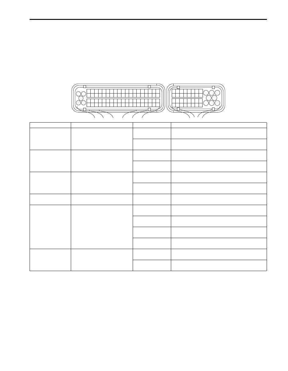
Voltage Check
Check voltage between the following terminals with ECM connector connected.
Terminal arrangement of ECM connector viewed from harness side
1
3 2
4
5
6
7
8
9
1110
12
13
14
15
16
17
18
19
20
17
18
19
20
21
22
23
24
25
26
27
28
29
30
31
33
34
35
36
37
38
39
40
32
1
2
3
4
5
6
7
8
9
10
11
12
13
14
15
16
21
22
23
24
25
26
27
28
29
30
31
32
33
34
35
36
37
38
39
40
41
42
43
44
45
46
47
48
49
50
51
52
53
54
55
56
57
58
59
60
61
62
63
64
65
66
67
68
69
70
71
72
73
74
75
76
77
78
79
80
81
C37
E23
I6JB01A10007-01
Terminals
Circuit
Normal Voltage
Condition
E23-30 – ground Brake light switch circuit
0 V
Ignition switch is at ON position and brake
pedal is not depressed.
10 – 14 V
Ignition switch is at ON position and brake
pedal is depressed.
E23-31 – ground
Cruise control MAIN (ON/
OFF) switch circuit
0 V
Ignition switch is at ON position and cruise
control MAIN (ON/OFF) switch is not pushed.
10 – 14 V
Ignition switch is at ON position and cruise
control MAIN (ON/OFF) switch is kept in push.
E23-32 – ground
Brake pedal position switch
circuit
10 – 14 V
Ignition switch is at ON position and brake
pedal is not depressed.
0 V
Ignition switch is at ON position and brake
pedal is depressed.
E23-38 – ground
Ground circuit for cruise
control command switch
Below 1.3 V
Ignition switch is at ON position.
E23-39 – ground
Cruise control command
switch (SET/COAST, ACC/
RES and CANCEL switch)
circuit
0 – 0.1 V
Ignition switch is at ON position and cruise
control CANCEL switch is kept in push.
1.5 – 1.9 V
Ignition switch is at ON position and SET/
COAST switch of cruise control is kept in push.
3.2 – 3.7 V
Ignition switch is at ON position and ACC/RES
switch of cruise control is kept in push.
4.5 – 5.5 V
Ignition switch is at ON position and cruise
control command switches are not pushed.
E23-40 – ground CPP switch circuit
10 – 14 V
Ignition switch is at ON position and clutch
pedal is not depressed.
0 V
Ignition switch is at ON position and clutch
pedal is depressed.
10A-16 Cruise Control System:
Repair Instructions
Cruise Control Switch Removal and Installation
S6JB0BA106001
For removal and installation, refer to “Remote Audio
Control Switch Removal and Installation (If Equipped) in
Section 9C”.
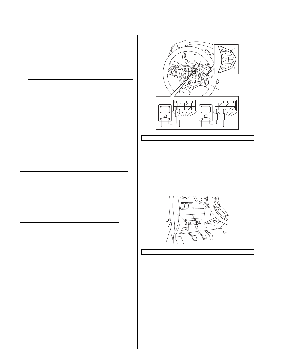
Cruise Control Switch Inspection
S6JB0BA106002
NOTE
Never disassemble cruise control switch.
Disassembly will spoil its original functions.
1) Remove driver air bag (inflator) module referring to
“Driver Air Bag (Inflator) Module Removal and
Installation in Section 8B”.
2) Disconnect cruise control switch connector (1) from
control coil.
3) Check cruise control switch as follow.
For MAIN (ON/OFF) Switch
Check for continuity between “1” and “8” terminals under
each condition below.
If check result is not satisfactory, replace cruise control
switch (2).
Cruise MAIN (ON/OFF) switch (3) specification: [B]
Switch button released: Infinity
Switch button pressed: Continuity
For SET/COAST, RES/ACC and CANCEL Switch
Check for resistance between “7” and “9” terminals
under each condition below.
If check result is not satisfactory, replace cruise control
switch (2).
SET/COAST, RES/ACC and CANCEL switches
resistance: [C]
All switches released (OFF): Infinity
CANCEL switch (4) pressed (ON): About 0
Ω
SET/COAST switch (5) pressed (ON): 209 – 231
Ω
RES/ACC switch (6) pressed (ON): 864 – 956
Ω
CPP Switch (for Cruise Control) Removal and
Installation
S6JB0BA106003
Removal
1) Disconnect connector of CPP switch (for cruise
control) (1) with ignition switch OFF.
2) Remove CPP switch (for cruise control) (1) from
pedal bracket.
[A]: Cruise control switch connector viewed from harness side
2. Brake light switch
1
5
3
6
7 8 9
1
5
3
6
7 8 9
[B]
[C]
[A]
6
1
4
5
2
3
I6JB0BA10004-01
1
2
I5JB0AA10007-01

Cruise Control System: 10A-17
Installation
1) Install CPP switch (for cruise control) (2) to pedal
bracket.
2) With clutch pedal (1) released, adjust switch position
so that clearance between end of thread and clutch
pedal bracket is within specification.
Clearance between end of thread and clutch
pedal bracket
“a”: 0.5 – 1.5 mm (0.02 – 0.06 in.) (LHD)
“a”: 2.0 – 3.0 mm (0.079 – 0.118 in.) (RHD)
3) Tighten lock nut (3) to specified torque.
Tightening torque
CPP switch lock nut: 7.5 N·m (0.75 kgf-m, 5.5 lb-
ft)
4) Connect connector to CPP switch (for cruise control)
(2) securely.
Clutch Pedal Position (CPP) Switch (for Cruise
Control) Inspection and Adjustment
S6JB0BA106004
Inspection
Check for resistance between terminals under each
condition below. If check result is not satisfactory,
replace.
CPP switch (for cruise control) resistance
When switch shaft is pushed [A]: No continuity
When switch shaft is free [B]: Continuity
Adjustment
For adjustment, refer to “Installation” under “CPP Switch
(for Cruise Control) Removal and Installation”.
Brake Light Switch Removal and Installation
S6JB0BA106005
For removal and installation, refer to “Brake Light Switch
Adjustment in Section 4A”.
Brake Light Switch Inspection
S6JB0BA106006
Check for continuity between terminals referring to
“Brake Light Switch Inspection in Section 9B”.
ECM Removal and Installation
S6JB0BA106007
For removal and installation, refer to “Engine Control
Module (ECM) Removal and Installation in Section 1C”.
Specifications
Tightening Torque Specifications
S6JB0BA107001
Reference:
For the tightening torque of fastener not specified in this section, refer to “Fastener Information in Section 0A”.
“a”
2
1
3
I5JB0AA10008-01
I5JB0AA10009-01
Fastening part
Tightening torque
Note
N
⋅m
kgf-m
lb-ft
CPP switch lock nut
7.5
0.75
5.5
Нет комментариевНе стесняйтесь поделиться с нами вашим ценным мнением.
Текст