Suzuki Grand Vitara JB627. Manual — part 428
10C-24 Immobilizer Control System:
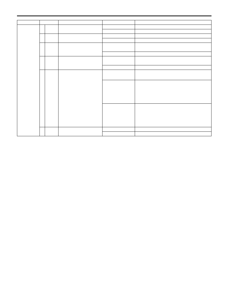
Connector Terminal
Circuit
Normal Voltage
Condition
G24
1
BLK/
WHT
Power supply
About 12.0 V
Ignition switch at ON position
0.0 V
Ignition switch at OFF position
2
BLK Ground
0.0 V
Ignition switch at ON position
0.0 V
Ignition switch at OFF position
3
GRY/
BLU
Serial communication line
See the reference
waveform.
—
0.0 V
Ignition switch at OFF position
4
PNK/
BLU
Clock line
See the reference
waveform.
—
0.0 V
Ignition switch at OFF position
5
BLK/
RED
Illumination ring ground
0 V
• Ignition key not inserted to the key cylinder
• Door opened
0 V
→ 12 V
• Ignition key at OFF position
• From the time door is closed to the time
interior light faded out completely
(As the interior light fades out, the voltage
increases.)
0 V
→ 12 V
• Door closed
• From the ignition switch is turned ON to the
time interior light is completely faded out
(As the interior light fades out, the voltage
increases.)
6 WHT
Illumination ring power
supply
About 12.0 V
Ignition switch at ON position
About 12.0 V
Ignition switch at OFF position
Immobilizer Control System: 10C-25
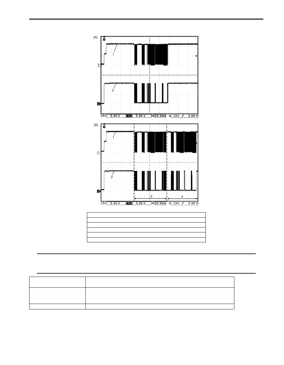
Reference Waveform
NOTE
When ECM cannot read the transponder code at the first try, ECM tries to read the transponder code
repeatedly up to 8 times. The second waveform is the example showing that ECM read the transponder
code successfully at the second try.
[A]: The transponder code read successfully at the first try.
[B]: The transponder code read successfully at the second try.
1. Serial communication line
2. Clock line
3. First try
4. Second try
Measurement terminals
CH1: G24-3 to G24-2
CH2: G24-4 to G24-2
Oscilloscope settings
CH1: 5 V/DIV
CH2: 5 V/DIV
TIME: 20 ms
Measurement condition
Right after the ignition switch is turned ON, the waveform can be read.
I4RS0AA30007-01
10C-26 Immobilizer Control System:
Repair Instructions
Immobilizer Control Module (ICM) Removal and
Installation
S6JB0BA306001
Removal
1) Disconnect negative (–) cable from battery.
2) Disable air bag system referring to “Disabling Air
3) Remove driver air bag (inflator) module referring to
“Driver Air Bag (Inflator) Module Removal and
Installation in Section 8B”.
4) Remove steering wheel referring to “Steering Wheel
Removal and Installation in Section 6B”.
5) Remove steering column lower and upper covers.
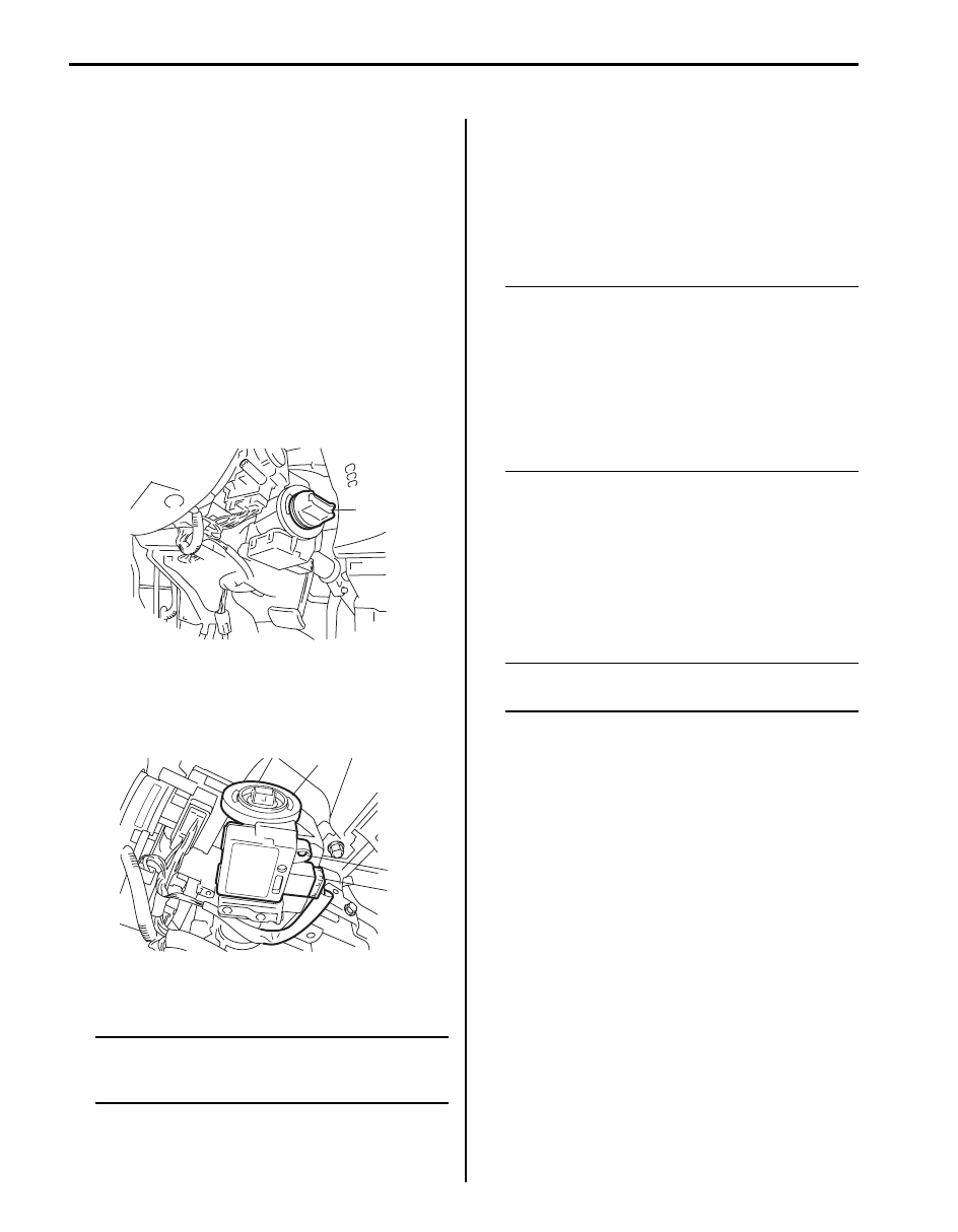
6) Remove engine start knob (1) if equipped with
keyless start system.
7) Disconnect connector (1) from immobilizer control
module (ICM) (2).
8) Remove a screw (3) from immobilizer control module
(ICM).
9) Remove immobilizer control module (ICM) from
steering lock assembly or steering lock unit.
NOTE
The antenna part of immobilizer control
module (ICM) is fragile. Therefore, do not add
strong power to the part or twist the part.
Installation
Reverse the removal procedure.
Registration of the Ignition Key
S6JB0BA306002
To finish the registration of the ignition key, the
transponder code memorized in the transponder built in
the ignition key has to be registered with ECM. To
register the transponder code with ECM, perform
“Register Ig Key” mode of SUZUKI scan tool referring to
“SUZUKI Tech 2 Operator’s Manual”.
NOTE
• A maximum of four transponder codes can
be registered with ECM.
• At an early part of the registration process,
all transponder codes of the ignition keys
in use already registered with ECM are
cleared. Therefore, before starting the
registration, prepare all ignition keys in
use in addition to the new ignition key(s) to
be registered with ECM.
Procedure after ECM Replacement
S6JB0BA306003
After ECM is replaced with new one or used one, the
transponder code in the transponder built in the ignition
key has to be registered with ECM. To register
transponder code in the ignition key with ECM, perform
“Replace New ECM” mode of SUZUKI scan tool
referring to “SUZUKI Tech 2 Operator’s Manual”.
NOTE
A maximum of four transponder codes can
be registered with ECM.
1
I5JB0AA30006-01
2
3
1
I4RS0BA30007-03
Immobilizer Control System: 10C-27
Special Tools and Equipment
Special Tool
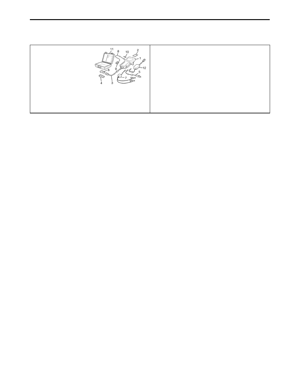
S6JB0BA308001
SUZUKI scan tool
—
This kit includes following
items. 1. Tech 2, 2. PCMCIA
card, 3. DLC cable, 4. SAE
16/19 adapter, 5. Cigarette
cable, 6. DLC loop back
adapter, 7. Battery power
cable, 8. RS232 cable, 9.
RS232 adapter, 10. RS232
loop back connector, 11.
Storage case, 12. ) / )
Нет комментариевНе стесняйтесь поделиться с нами вашим ценным мнением.
Текст