Suzuki Grand Vitara JB627. Manual — part 427

10C-20 Immobilizer Control System:
DTC P1625: Immobilizer Antenna Error
S6JB0BA304015
Wiring Diagram
Refer to “Immobilizer Control System Wiring Circuit Diagram”
Detecting Condition and Trouble Area
Troubleshooting
3
Registration of the unregistered ignition key with ECM
and Diagnostic Trouble Code (DTC) check
1) Register the transponder code in the transponder in the
unregistered ignition key with ECM referring to
“Registration of the Ignition Key”.
2) Check if that DTC P1623 is detected referring to
“Diagnostic Trouble Code (DTC) Check”.
Is DTC P1623 detected?
Go to Step 4.
The troubleshooting is
completed.
4
Immobilizer control module (ICM) check
1) Check immobilizer control module (ICM) referring to
“Inspection of Immobilizer Control Module (ICM) and Its
Circuit”.
Is immobilizer controller assembly normal?
Replace ECM with new
one referring to “Engine
Control Module (ECM)
Removal and
Installation in Section
1C”, and then perform
“Procedure after ECM
Replacement”.
Replace immobilizer
control module (ICM)
with new one referring
to “Immobilizer Control
Module (ICM) Removal
and Installation”.
Step
Action
Yes
No
Detecting Condition
Trouble Area
Immobilizer control module (ICM) is faulty.
• Immobilizer control module faulty
• ECM faulty
Step
Action
Yes
No
1
Diagnostic Trouble Code (DTC) confirmation
1) Clear DTC(s) referring to “Diagnostic Trouble Code
2) Turn the ignition switch to OFF position.
3) Check if any DTC is detected referring to “Diagnostic
Is DTC P1625 still detected?
Go to Step 2.
The troubleshooting is
completed.
2
Immobilizer control module (ICM) replacement and
Diagnostic Trouble Code (DTC) check
1) Replace immobilizer control module (ICM) referring to
“Immobilizer Control Module (ICM) Removal and
Installation”.
2) Check if DTC P1625 is still detected referring to
“Diagnostic Trouble Code (DTC) Check”.
Is DTC P1625 still detected?
Replace ECM with new
one referring to “Engine
Control Module (ECM)
Removal and
Installation in Section
1C”, and then perform
“Procedure after ECM
Replacement”.
The troubleshooting is
completed.

Immobilizer Control System: 10C-21
DTC P1636: Immobilizer Information Registration Failure
S6JB0BA304016
Wiring Diagram
Refer to “Immobilizer Control System Wiring Circuit Diagram”
DTC Detecting Condition and Trouble Area
Troubleshooting
Detecting Condition
Trouble Area
The registration of the immobilizer control system
information in ECM is failed.
• CAN communication wire circuits faulty
• Steering angle sensor (if equipped) faulty
• Keyless start control module (if equipped) faulty
• 4WD control module (if equipped) faulty
• TCM (if equipped) faulty
• BCM faulty
• ABS/ESP
® control module faulty
• Combination meter faulty
• ECM faulty
Step
Action
Yes
No
1
Diagnostic Trouble Code (DTC) confirmation
1) Clear DTC(s) referring to “Diagnostic Trouble Code
2) Turn the ignition switch to OFF position.
3) Check if any DTC is detected referring to “Diagnostic
Is DTC P1636 still detected?
Go to Step 2.
The troubleshooting is
completed.
2
Diagnostic Trouble Code (DTC) check in ECM
Is any DTC other than P1636 detected in Step 1?
Perform the
troubleshooting
referring to the
corresponding
flowchart.
Go to Step 3.
3
Diagnostic Trouble Code (DTC) check in BCM
1) Check BCM for DTC referring to “DTC Check in Section
10B”.
Is any DTC detected?
Perform the
troubleshooting
referring to the
corresponding flowchart
in Section 10B.
Go to Step 4.
4
Replacement of BCM
1) Replace BCM with new one referring to “BCM Removal
and Installation in Section 10B”.
2) Check ECM for DTC referring to “Diagnostic Trouble
Is DTC P1636 still detected?
Go to Step 5.
The troubleshooting is
completed.
5
Replacement of ECM
1) Replace ECM with new one referring to “Engine Control
Module (ECM) Removal and Installation in Section 1C”.
2) Check ECM for DTC referring to “Diagnostic Trouble
Is DTC P1636 still detected?
Recheck CAN
communication wire
circuits and poor
connection at ECM,
ABS/ESP
® control
module and BCM
connectors.
The troubleshooting is
completed.

10C-22 Immobilizer Control System:
DTC P1638: Immobilizer Information Mismatched
S6JB0BA304017
Wiring Diagram
Refer to “Immobilizer Control System Wiring Circuit Diagram”
DTC Detecting Condition and Trouble Area
Troubleshooting
Detecting Condition
Trouble Area
• The immobilizer control system information in ECM and
the one in BCM does not match.
• The registration of the immobilizer control system
information in ECM is failed.
• Use of the wrong ECM
• Steering angle sensor (if equipped) faulty
• Keyless start control module (if equipped) faulty
• 4WD control module (if equipped)
• TCM (if equipped) faulty
• CAN communication wire circuits faulty
• BCM faulty
• Combination meter faulty
• ABS/ESP
® control module faulty
• ECM faulty
Step
Action
Yes
No
1
Diagnostic Trouble Code (DTC) confirmation
1) Clear DTC(s) referring to “Diagnostic Trouble Code
2) Turn the ignition switch to OFF position.
3) Check if any DTC is detected referring to “Diagnostic
Is DTC P1638 still detected?
Go to Step 2.
The troubleshooting is
completed.
2
Diagnostic Trouble Code (DTC) confirmation
1) Disconnect negative (–) cable from battery for more than
5 seconds.
2) Connect negative (–) cable to battery.
3) Check if any DTC is detected referring to “Diagnostic
Is DTC P1638 still detected?
Go to Step 3.
The troubleshooting is
completed.
3
Check ECM specification
1) Check ECM part number to see if ECM is applicable to
the vehicle in service.
Is a correct ECM used for the vehicle in service?
Go to Step 2.
Replace ECM with the
correct one and recheck
if DTC P1638 is still
detected by ECM.
4
Diagnostic Trouble Code (DTC) check in ECM
Is any DTC other than P1638 detected in Step 1?
Perform the
troubleshooting
referring to the
corresponding
flowchart.
Go to Step 3.
5
Diagnostic Trouble Code (DTC) check in BCM
1) Check BCM for DTC referring to “DTC Check in Section
Is any DTC detected?
Perform the
troubleshooting
referring to the
corresponding flowchart
in Section 10B.
Go to Step 5.
Immobilizer Control System: 10C-23
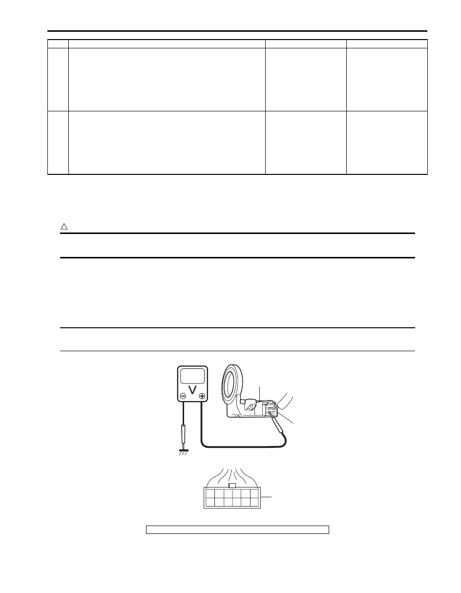
Inspection of Immobilizer Control Module (ICM) and Its Circuit
S6JB0BA304018
Immobilizer control module (ICM) and its circuit can be checked at immobilizer control module (ICM) wiring connector
by measuring voltage.
CAUTION
!
Immobilizer control module (ICM) cannot be checked by itself. It is strictly prohibited to connect
voltmeter or ohmmeter to immobilizer control module (ICM) with connector disconnected from it.
Voltage Check
1) Remove immobilizer control module (ICM) (1) from steering lock assembly or steering lock unit referring to
“Immobilizer Control Module (ICM) Removal and Installation”.
2) Connect immobilizer control module (ICM) connector (2) to immobilizer control module (ICM).
3) Check voltage at each terminal.
NOTE
As each terminal voltage is affected by the battery voltage, confirm that it is 11 V or more when the
ignition switch is turned to ON position.
6
Replacement of BCM
1) Replace BCM with new one referring to “BCM Removal
and Installation in Section 10B”.
2) Check ECM for DTC referring to “Diagnostic Trouble
Is DTC P1638 still detected?
Go to Step 6.
The troubleshooting is
completed.
7
Replacement of ECM
1) Replace ECM with new one referring to “Engine Control
Module (ECM) Removal and Installation in Section 1C”.
2) Check ECM for DTC referring to “Diagnostic Trouble
Is DTC P1638 still detected?
Recheck CAN
communication wire
circuits and poor
connection at ECM,
ABS/ESP
® control
module and BCM
connectors.
The troubleshooting is
completed.
Step
Action
Yes
No
3. Immobilizer control module (ICM) connector (harness side view)
1
2
3
4
G24
1
2
3
5
6
I5JB0AA30005-01
Нет комментариевНе стесняйтесь поделиться с нами вашим ценным мнением.
Текст