Suzuki Grand Vitara JB627. Manual — part 228
5A-96 Automatic Transmission/Transaxle:
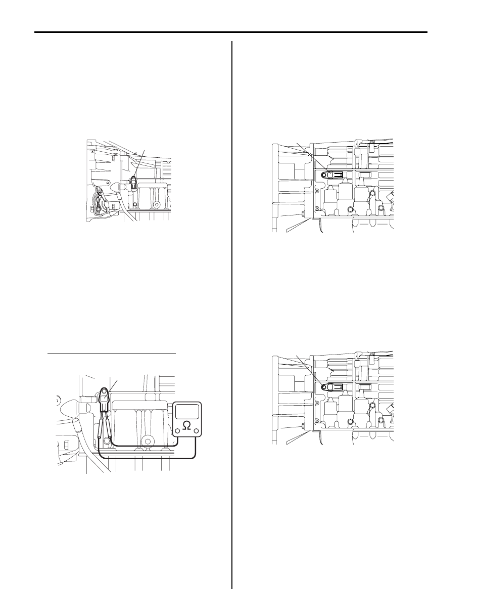
Installation
1) Check that sensor is free from any metal particles
and damage.
2) Apply A/T fluid to new O-ring and then install input
shaft speed sensor (1) to transmission.
Tighten sensor bolt to specified torque.
Tightening torque
Input shaft speed sensor bolt (a): 5.5 N·m (0.55
kgf-m, 4.0 lb-ft)
3) Connect input shaft speed sensor connector.
4) Lower hoist.
5) Connect negative cable at battery.
Input Shaft Speed Sensor Inspection
S6JB0B5106018
1) Disconnect negative cable at battery.
2) Hoist vehicle.
3) Disconnect input shaft speed sensor connector.
4) Check input shaft speed sensor (1) for resistance
between terminals of sensor.
Input shaft speed sensor resistance
Standard: 560 – 680
Ω (at 20 °C (68 °F))
Output Shaft Speed Sensor Removal and
Installation
S6JB0B5106019
Removal
1) Disconnect negative cable at battery.
2) Hoist vehicle.
3) Disconnect output shaft speed sensor connector.
4) Remove output shaft speed sensor (1) from
transmission.
Installation
1) Check that sensor is free from any metal particles
and damage.
2) Apply A/T fluid to new O-ring and then install output
shaft speed sensor (1) to transmission.
Tighten sensor bolt to specified torque.
Tightening torque
Output shaft speed sensor bolt (a): 5.5 N·m (0.55
kgf-m, 4.0 lb-ft)
3) Connect output shaft speed sensor connector.
4) Lower hoist.
5) Connect negative cable at battery.
1, (a)
I4JA01512019-01
1
I4JA01512020-01
1
I4JA01512021-01
1, (a)
I4JA01512022-01
Automatic Transmission/Transaxle: 5A-97
Output Shaft Speed Sensor Inspection
S6JB0B5106020
1) Disconnect negative cable at battery.
2) Hoist vehicle.
3) Disconnect output shaft speed sensor connector.
4) Check output shaft speed sensor (1) for resistance
between terminals of sensor.
Output shaft speed sensor resistance
Standard: 560 – 680
Ω (at 20 °C (68 °F))
Solenoid Valves (Shift Solenoid-A, Shift
Solenoid-B, Shift Solenoid-E, TCC Solenoid,
Pressure Control Solenoid-A, Pressure Control
Solenoid-B, and Pressure Control Solenoid-C)
Removal and Installation
S6JB0B5106021
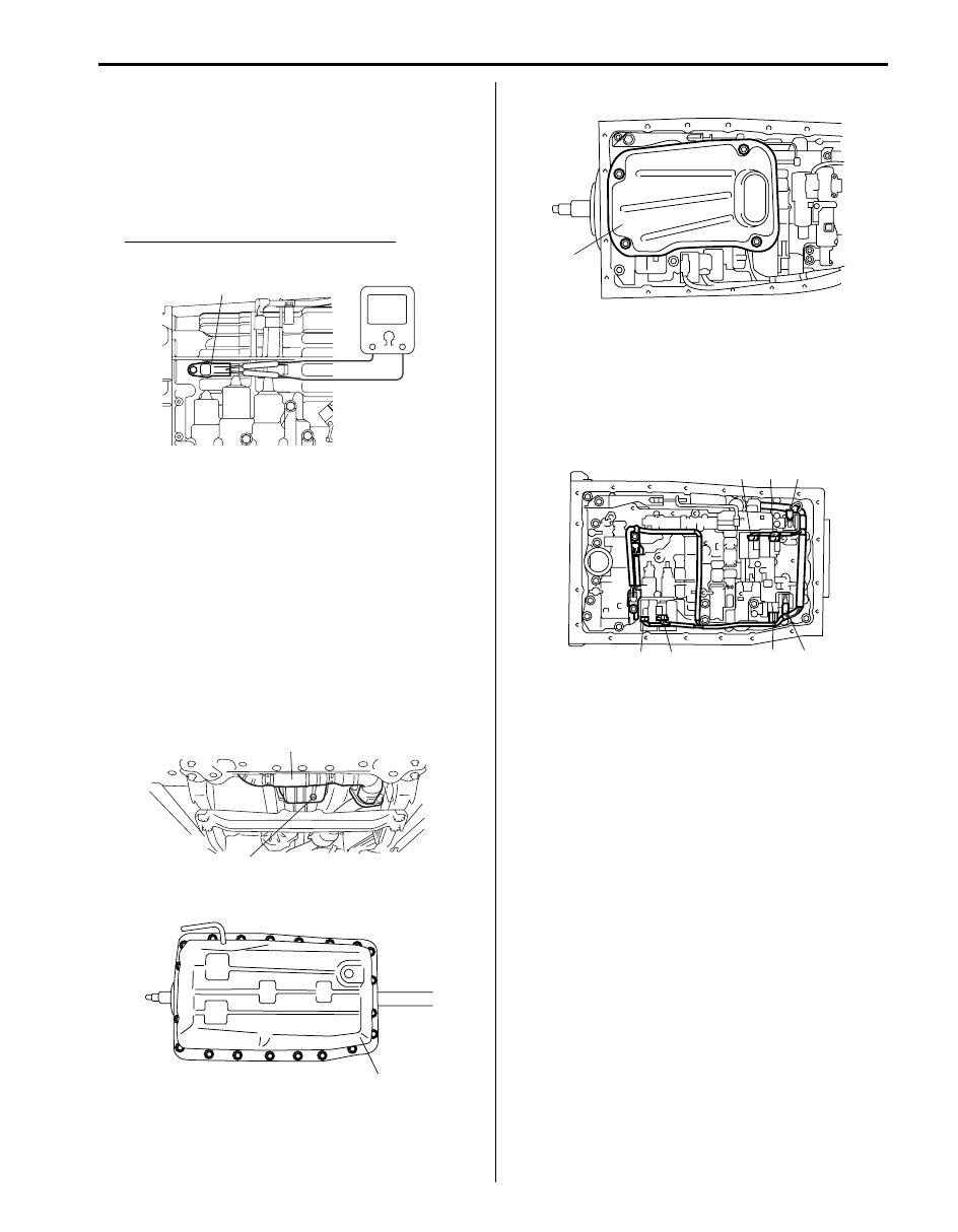
Removal
1) Disconnect negative cable at battery.
2) Pull out fluid level gauge and lift up vehicle.
3) Remove exhaust No.1 pipe (1).
4) Remove drain plug (2) and drain A/T fluid.
5) Install drain plug (2).
6) Remove A/T oil pan (1).
7) Remove A/T oil strainer (1).
8) Disconnect shift solenoid-A connector (1), shift
solenoid-B connector (2), shift solenoid-E connector
(3), TCC solenoid connector (4), Pressure control
solenoid-A connector (5), Pressure control solenoid-
B connector (6) and Pressure control solenoid-C
connector (7).
9) Remove solenoid valves.
Installation
Remove removal procedure to install solenoid valves,
noting the following points.
• For details of solenoid valves and their connectors
installation, refer to “Automatic Transmission Unit
Assembly”. Use new O-ring.
• For details of A/T oil pan installation, refer to
“Automatic Transmission Unit Assembly”.
• Tighten exhaust No.1 pipe bolts & nuts and exhaust
bracket bolts & nuts.
• Fill A/T fluid and check fluid level according to
procedure described in “A/T Fluid Change”.
• Check for fluid leakage after warming up A/T.
1
I4JA01512023-01
2
1
I6JB01510026-01
1
I4JA01512025-01
1
I4JA01512026-01
7
5
3
1
2
4
6
I4JA01512027-01
5A-98 Automatic Transmission/Transaxle:
Solenoid Valves (Shift Solenoid-A, Shift
Solenoid-B, Shift Solenoid-E, TCC Solenoid,
Pressure Control Solenoid-A, Pressure Control
Solenoid-B, and Pressure Control Solenoid-C)
Inspection
S6JB0B5106022
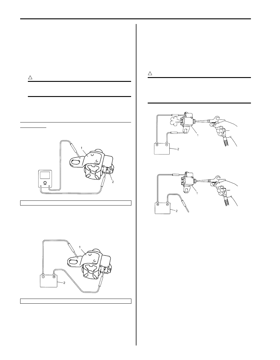
Solenoid Valves (Shift Solenoid-A, Shift Solenoid-B
and Shift Solenoid-E)
Resistance check
CAUTION
!
Be very careful as dust etc. does not enter
when solenoid valves are inspected.
Measure resistance between terminal (2) and solenoid
valve body. If resistance is out of specification, replace
solenoid valve.
Shift solenoid-A, Shift solenoid-B and Shift solenoid-
E resistance
Standard: 11 – 15
Ω (at 20 °C (68 °F))
Operation Check
• With solenoid connected to battery (2) as shown in the
figure, check that solenoid valve is actuated with click
sound.
• With shift solenoid valve (1) connected to battery (2),
confirm that shift solenoid valve is open by blowing air
(50 – 200 kPa, 0.5 – 2.0 kg/cm
2
, 7 – 28.5 psi) into
solenoid valve as shown in the figure.
• With shift solenoid valve (1) not connected to battery
(2), confirm that shift solenoid valve is closed by
blowing air (50 – 200 kPa, 0.5 – 2.0 kg/cm
2
, 7 – 28.5
psi) into solenoid valve as shown in the figure.
CAUTION
!
Do not insert air gun against strainer
installed on inlet of solenoid valve too deeply,
when blowing air into solenoid valve. If not,
the strainer will be damaged.
1. Shift solenoids
1. Shift solenoids
I4JA01512029-01
I4JA01512030-01
I4JA01512031-01
Automatic Transmission/Transaxle: 5A-99
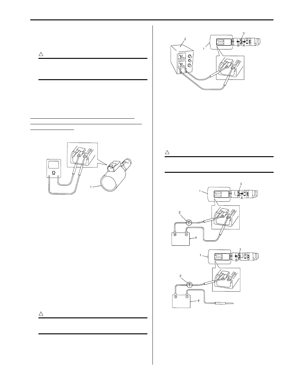
Pressure Control Solenoid Valves (Pressure Control
Solenoid-A, Pressure Control Solenoid-B, Pressure
Control Solenoid-C and TCC Solenoid Valve)
Resistance check
CAUTION
!
Be very careful as dust etc. does not enter
when pressure control solenoid valves are
inspected.
Measure resistance between pressure control solenoid
valves (Pressure control solenoid-A, Pressure control
solenoid-B, Pressure control solenoid-C and TCC
solenoid) (1) terminals. If resistance is out of
specification, replace valve body assembly.
Pressure control solenoid-A, Pressure control
solenoid-B, Pressure control solenoid-C and TCC
solenoid resistance
Standard: 5.0 – 5.6
Ω (at 20 °C (68 °F))
Operation check
Check pressure control solenoid valves (Pressure
control solenoid-A, Pressure control solenoid-B,
Pressure control solenoid-C and TCC solenoid) (1)
operation in either of the following methods.
[Using regulated DC power supply]
1) Connect pressure control solenoid valve (1) with
regulated DC power supply (2) as shown in the
figure.
2) Turn regulated DC power supply switch ON,
increase voltage of power supply keeping current
within 1.0 A.
3) Check that valve (3) moves gradually in arrow “A”
direction as voltage increases.
4) Check that valve (3) moves in arrow “B” direction as
voltage decreases.
5) Turn power supply switch OFF.
CAUTION
!
Do not feed current 1.0 A or more, or
pressure control solenoid will be burned out.
[Not using regulated DC power supply]
1) Connect pressure control solenoid valve (1) to
battery (4) setting 21 W bulb (2) in between as
shown in the figure.
2) Check that valve (3) moves in arrow “A” direction.
3) Disconnect pressure control solenoid valve (1) from
battery (4) and check that valve (3) moves in arrow
“B” direction as shown in the figure.
CAUTION
!
Set 21 W bulb in between, or pressure control
solenoid valve will be burned out.
I4JA01512032-01
I4JA01512033-01
I4JA01512034-01
Нет комментариевНе стесняйтесь поделиться с нами вашим ценным мнением.
Текст