Suzuki Grand Vitara JB627. Manual — part 415

10B-9 Body Electrical Control System:
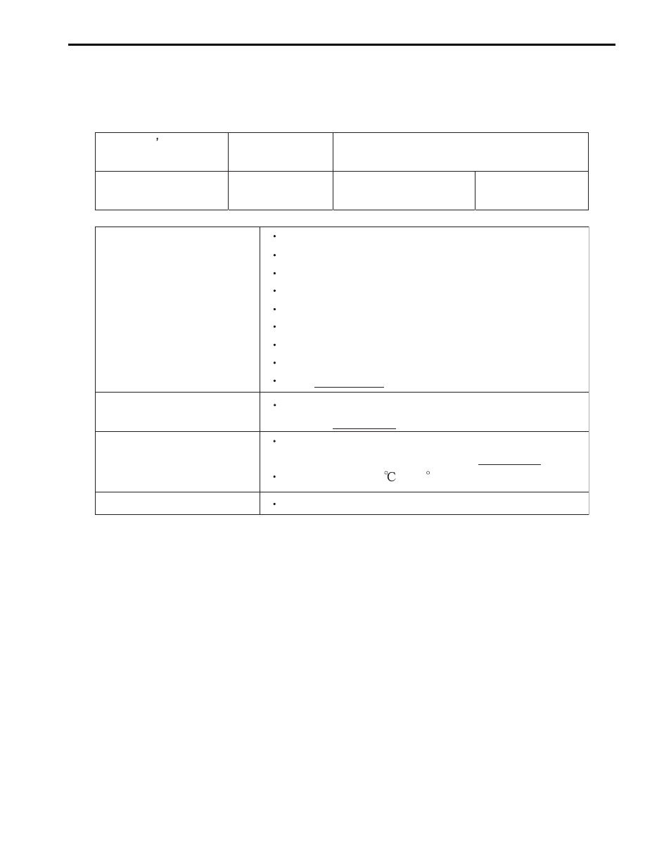
Body Electrical Control System Check
S6JB0BA204002
Step
Action
Yes
No
1
Customer complaint analysis
1) Perform customer complaint analysis.
Was customer complaint analysis performed?
Go to Step 2.
Perform customer
complaint analysis.
2
Problem symptom confirmation
1) Perform problem symptom confirmation.
Does trouble recur?
Go to Step 3.
Go to Step 7.
3
DTC check
1) Check DTC.
Is it malfunction code?
Go to Step 4.
Go to Step 5.
4
Troubleshooting for DTC
1) Check and repair according to DTC diag. flow.
Are check and repair completed?
Go to Step 7.
Check and repair
malfunction part(s).
5
Body electrical control system symptom diagnosis
1) Perform check and repair referring to “Symptom
Diagnosis” of system having a trouble.
Is there faulty condition?
Repair or replace
malfunction part(s).
Go to Step 6.
6
Check for intermittent problem
1) Check for intermittent problem.
Is there faulty condition?
Repair or replace
malfunction part(s).
Go to Step 7.
7
Final confirmation test
1) Clear DTC referring to “DTC Clearance”.
2) Check DTC referring to “DTC Check”.
Is there any DTC?
Go to Step 4.
End.
Body Electrical Control System: 10B-10
Customer Complaint Analysis
Record details of the problem (failure, complaint) and how it occurred as described by the customer.
For this purpose, use of such a questionnaire form as shown in the figure will facilitate collecting information to the
point required for proper analysis and diagnosis.
Customer questionnaire (example)
Problem Symptom Confirmation
Check if what the customer claimed in “Customer Questionnaire” is accurately found in the vehicle. If that symptom is
found, check whether the symptom is identified as a failure. (This step should be shared with the customer if possible.)
DTC Check
Check DTC stored in BCM memory referring to “DTC Check”, record it and then clear it referring to “DTC Clearance”.
DTC indicates malfunction that occurred in the system but does not indicate whether it exists now or it occurred in the
past and the normal condition has been restored now. To check which case applies, clear DTC once and check
whether or not any fault exists.
Troubleshooting for DTC
Based on the DTC indicated in Step 3 and referring to applicable DTC flow, locate the cause of the trouble, namely in
a sensor, wire harness, connector, BCM or other part and repair or replace faulty parts.
Body Electrical Control System Symptom Diagnosis
Check the parts or system suspected as a possible cause referring to symptom diagnosis of each system.
Check for Intermittent Problem
Check parts where an intermittent trouble is easy to occur (e.g., wire harness, connector, etc.), referring to
“Intermittent and Poor Connection Inspection in Section 00”.
Customer s name:
Model:
VIN:
Date of issue:
Date Reg:
Date of problem:
Mileage:
Problem Symptoms
Power door lock system does not operate
Keyless entry system does not operate
Rear end door window defogger does not operate
Rear wiper does not operate
Rear end door opener does not operate
Other
Frequency of Occurrence
Continuous / Intermittent ( times a day, a month)
/
Other
Environmental Condition
Weather:
Fine / Cloudy / Rain / Snow / Other
Temperature:
(
F )
Diagnostic Trouble Code
Normal code / Malfunction code ( )
Warning buzzer does not sound
Interior light does not light
Theft deterrent light does not flush
I5RS0DA20006-01
10B-11 Body Electrical Control System:
Final Confirmation Test
Confirm that the problem symptom has gone and the body electrical control system is free from any abnormal
conditions. If what has been repaired is related to the malfunction DTC, check DTC again and confirm that no DTC is
indicated.
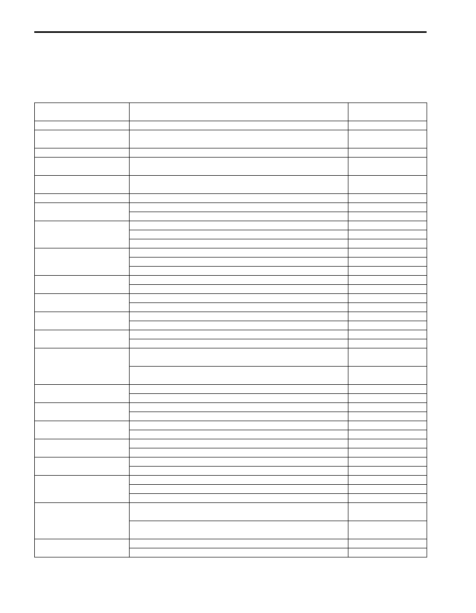
Scan Tool Data
S6JB0BA204003
Scan tool Data
Condition
Normal condition /
reference value
Vehicle Speed
At stop with ignition switch turned ON
0 km/h
Outside air Temp
Reference value is relative to outside air temperature
–40
°C – 70 °C
(–40
°F – 158 °F)
Battery Voltage
At specified idle speed after warming up
10 – 14 V
Coolant Temp
At specified idle speed after warming up
80
°C – 100 °C
(176
°F – 212 °F)
Engine Speed
Engine idling with no load applied after warming up
Desired idle speed
± 50 rpm
Fuel Consumption
At specified idle speed after warming up
0.0 km/l
Key Reminder Sw
Ignition key inserted in ignition key cylinder
Key in
Ignition key pulled out from ignition key cylinder
Pulled
Door key Sw
Key cylinder switch of driver side door at lock position
LOCK
Key cylinder switch of driver side door not turned
Neutral
Key cylinder switch of driver side door at unlock position
Unlock
Door Lock Sw
Lock side of manual door lock switch pressed
LOCK
Manual door lock switch not pressed
Neutral
Unlock side of manual door lock switch pressed
Unlock
Driv Door Sw
Driver side door open
Open
Driver side door closed
Close
Pass Door Sw
Doors other than driver side door open
Open
Doors other than driver side door closed
Close
Brake Fluid Level
Brake fluid level at MIN level or higher
Normal
Brake fluid level lower than MIN level
Low
Parking Brake Sw
Parking brake lever pulled
ON
Parking brake lever released
OFF
Rear Defogger Sw
Rear end door window defogger switch turned ON with engine
running
ON
Rear end door window defogger switch turned OFF with engine
running
OFF
Tail Light Sw
Lighting switch at HEAD or CLEARANCE position
ON
Lighting switch at OFF position
OFF
Driv Seat belt Sw
Driver side seat belt fastened
Fasten
Driver side seat belt unfastened
Unfasten
Charge Light
Engine at stop with ignition switch turned ON
ON
Engine running
OFF
Oil pressure switch
Engine at stop with ignition switch turned ON
ON
Engine running
OFF
A/C Switch
A/C and ignition switch turned ON
ON
A/C switch turned OFF
OFF
Rear Wiper Sw
Rear wiper switch at ON position
ON
Rear wiper switch at INT position
INT
Rear wiper switch at OFF position
OFF
Front Fog Light Sw
Lighting switch at HEAD or CLEARANCE position and front fog
light switch at ON position
ON
Lighting switch at HEAD or CLEARANCE position and front fog
light switch at OFF position
OFF
Headlight Sw
Lighting switch at HEAD position
ON
Lighting switch at OFF position
OFF
Body Electrical Control System: 10B-12
Scan Tool Data Definitions
Vehicle Speed (km/h, mph): This parameter indicates the vehicle speed computed by ECM.
Outside air Temp (
°C, °F): It is detected by outside air temperature sensor.
Battery Voltage (V): This parameter indicates battery positive voltage inputted to BCM.
Coolant Temp (Engine coolant temperature) (
°C, °F): This parameter indicates the engine coolant temperature
computed by ECM.
Engine Speed (RPM): This parameter indicates the engine speed computed by ECM.
Fuel Consumption (km/l): This parameter indicates the fuel consumption computed by ECM.
Key Reminder Sw (Key reminder switch) (Pulled / Key in): This parameter indicates the state of the key reminder
switch.
Door key Sw (Door key cylinder switch) (Lock / Neutral / Unlock): This parameter indicates the state of the door
key cylinder switch.
Door lock Sw (Manual door lock switch) (Lock / Neutral / Unlock): This parameter indicates the state of the
manual door lock switch.
Driv Door Sw (Driver side door switch) (Open / Close): This parameter indicates the state of the driver side door
switch.
Pass Door Sw (Other than driver side door switch) (Open / Close): This parameter indicates the state of the door
switches other than driver side door switch.
Brake Fluid Level (Low / Normal): Low: Brake fluid level is lower than specified level.
Normal: Brake fluid level is higher than MIN level.
Parking Brake Sw (Parking brake switch) (ON / OFF): ON: Parking brake lever is pulled up.
OFF: Parking lever is released
Rear Defogger Sw (Rear end door window defogger switch) (ON / OFF): This parameter indicates the state of
the rear end door window defogger switch.
Tail Light Sw (Lighting switch) (ON / OFF): This parameter indicates the state of the lighting switch.
Driv Seat belt Sw (Driver seat belt switch) (Fasten / Unfasten): This parameter indicates the state of the driver
side seat belt buckle switch.
Charge light (ON / OFF): This parameter indicates the state of the charge system monitor switch.
Oil pressure switch (ON / OFF): This parameter indicates the state of the oil pressure switch.
A/C Switch (ON / OFF): This parameter indicates the state of the air conditioning switch.
Rear Wiper Sw (Rear wiper switch) (ON / INT / OFF): This parameter indicates the state of the rear wiper switch.
Front Fog Light Sw (Front fog light switch) (ON / OFF): This parameter indicates the state of the front fog light
switch.
Headlight Sw (Headlight switch) (ON / OFF): This parameter indicates the state of the lighting switch.
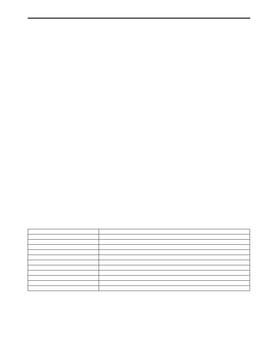
Diagnosis Using Output Test Function of SUZUKI Scan Tool
SUZUKI scan tool has the output test function which can force operation of following actuators and relays of the
system controlled by BCM. When a malfunction is found in the system controlled by BCM, execute the output test
which enables easy judgment whether the malfunction is on the input side or output side of BCM. For detailed
information on operation of SUZUKI scan tool, refer to “SUZUKI Scan Tool Operator’s Manual”.
Output Test Item
Controlled Parts
Hazard Warning Light
Turn signal and hazard warning relay
Interior (Dome) Light
Interior (Dome) light (when interior light switch is at DOOR position)
Parking/Tail Light
Tail light relay
Front Fog Light
Front fog light relay (when lighting switch is at CLEARANCE position)
Rear defogger
Rear defogger and mirror heater relays
D.R.L.
Headlight low beam relay
Auto on headlight
Headlight low beam and tail light relays
Door
Each door lock actuator
Warning buzzer
Warning buzzer (in BCM)
Rear wiper
Rear wiper relay
Alarm indicator
Theft deterrent light (in HVAC control module)
Нет комментариевНе стесняйтесь поделиться с нами вашим ценным мнением.
Текст