Suzuki Grand Vitara JB627. Manual — part 176
4B-4 Front Brakes:
2) Install caliper and tighten caliper (slide) pin bolts (1)
to specification.
NOTE
Make sure that boots are fit into groove
securely.
Tightening torque
Caliper pin bolt (a): 36 N·m (3.6 kgf-m, 26.0 lb-ft)
3) Install front wheel referring to “Wheel Removal and
4) Upon completion of installation, perform brake test.
Front Brake Disc and Pad Inspection
S6JB0B4206004
Brake Pad
Check pad lining for wear. When wear exceeds limit,
replace with new one.
CAUTION
!
Never polish pad lining with sandpaper. If
lining is polished with sandpaper, hard
particles of sandpaper will be deposited in
lining and may damage disc. When pad lining
requires correction, replace it with a new one.
NOTE
When pads are removed, visually inspect
caliper for brake fluid leak. Correct leaky
point, if any.
Front disc brake pad thickness (lining thickness)
Standard: 11.0 mm (0.43 in.)
Limit: 2.0 mm (0.08 in.)
Brake Disc
Before this inspection, brake pads must be removed.
Check disc surface for scratches in wearing parts.
Scratches on disc surface noticed at the time of
specified inspection or replacement are normal and disc
is not defective unless they are serious.
But when there are deep scratches or scratches all over
disc surface, replace it. When only one side is scratched,
polish and correct that side.
Front brake disc thickness “a”
Standard: 25 mm (1.020 in.)
Limit: 23 mm (0.905 in.)
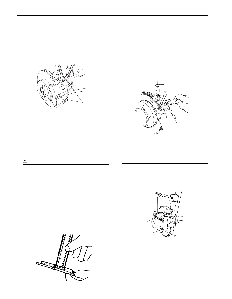
Use wheel nuts (1) and suitable plain washers (2) to hold
the disc securely against the hub, then mount a dial
gauge (3) as shown in the figure and measure the runout
at 25 mm (0.98 in.) from the outer edge of the disc.
NOTE
Check front wheel bearing for looseness
before measurement.
Front brake disc deflection
Limit: 0.1 mm (0.004 in.)
1,(a)
I5JB0A420005-01
I2RH01420005-01
IYSQ01420008-01
IYSQ01420009-01
Front Brakes: 4B-5
Slide Pin Bolt / Cylinder Slide Pin
Check slide pin (bolt) for smooth movement as shown in
the figure.
If it is found faulty, correct or replace. Apply grease
(included with new pin boot) to slide pin (bolt) outer
surface.
Slide Pin Boot
Check boot for breakage, crack and damage. If
defective, replace.
Front Disc Brake Caliper Removal and
Installation
S6JB0B4206005
CAUTION
!
Be careful not to twist flexible hose while
loosening the bolt.
Removal
1) Hoist vehicle and remove front wheel.
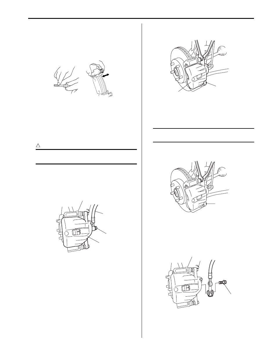
2) Remove brake flexible hose mounting bolt (1) from
caliper (2). As this will allow fluid to flow out of hose
(3), have a container ready beforehand.
3) Remove caliper pin bolts (1).
4) Remove caliper (2).
Installation
1) Install caliper to caliper carrier.
Then tighten pin bolts to specified torque.
NOTE
Make sure that boots are fit into groove
securely.
Tightening torque
Caliper pin bolt (a): 36 N·m (3.6 kgf-m, 26.0 lb-ft)
2) Install brake flexible hose and new hose washer as
shown and tighten flexible hose joint bolt (1) to
specification.
Tightening torque
Flexible hose joint bolt (a): 23 N·m (2.3 kgf-m,
17.0 lb-ft)
IYSQ01420021-01
1
2
3
I5JB0A420006-01
1
2
I5JB0A420007-01
1,(a)
I5JB0A420008-01
1,(a)
I5JB0A420009-02
4B-6 Front Brakes:
3) Install front wheel referring to “Wheel Removal and
4) After completing installation, fill reservoir with
specified brake fluid and bleed brake system. Check
each installed part for oil leakage and perform brake
test.
Front Disc Brake Caliper Disassembly and
Assembly
S6JB0B4206006
Disassembly
NOTE
Before disassembly, clean all around caliper
with brake fluid.
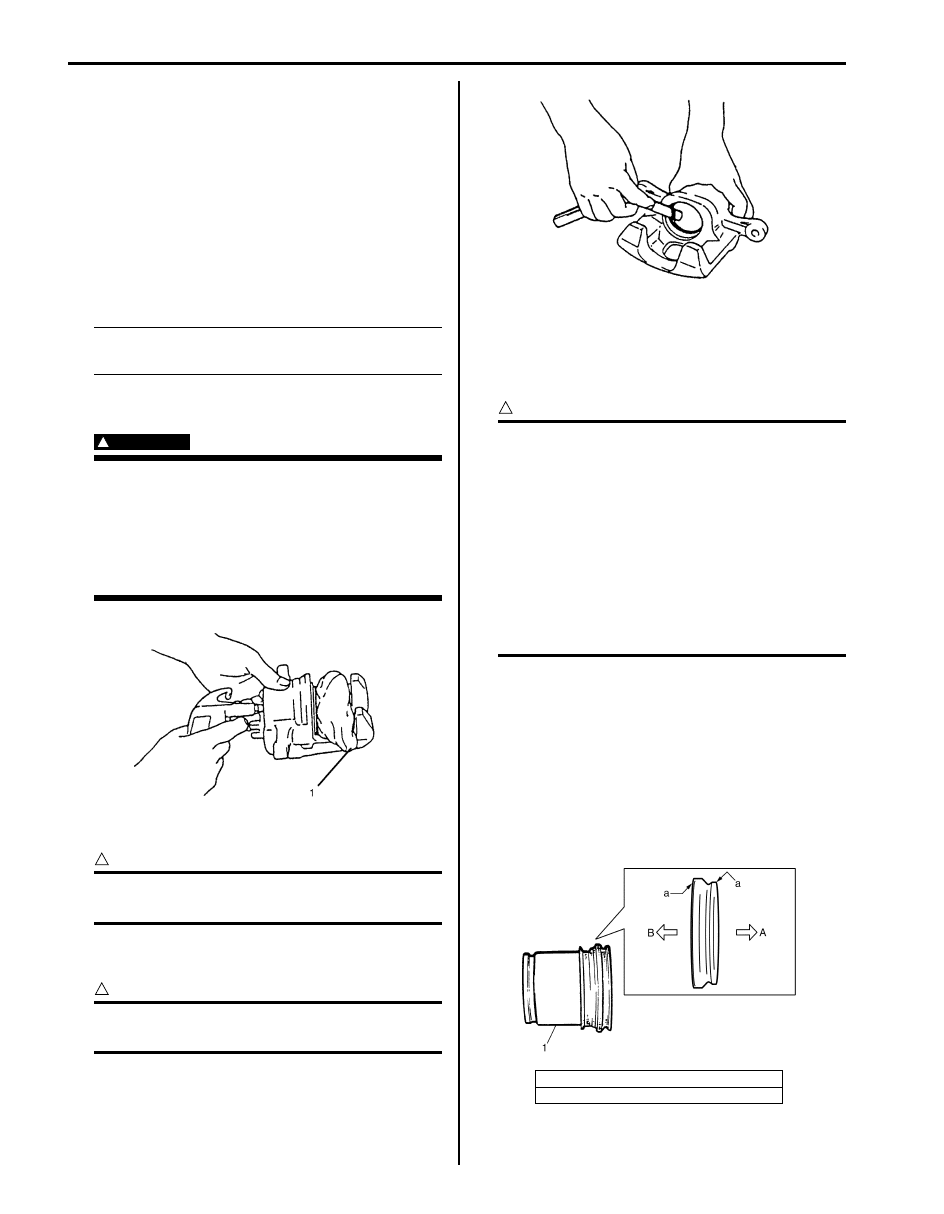
1) Remove disc brake piston with air blown into flexible
hose joint bolt installation hole.
WARNING
!
Do not apply too highly compressed air
which will cause piston to jump out of
cylinder. Place a cloth (1) to prevent piston
from damage, it should be taken out
gradually with moderately compressed air.
Do not place your fingers in front of piston
when using compressed air.
2) Remove cylinder boot.
CAUTION
!
Be careful not to damage inside (bore side) of
cylinder.
3) Remove piston seal using a thin blade like a
thickness gauge, etc.
CAUTION
!
Be careful not to damage inside (bore side) of
cylinder.
4) Remove bleeder plug and cap from caliper.
Assembly
Reassemble front brake in reverse order of disassembly,
noting the following points.
CAUTION
!
• Wash each part cleanly before installation
in the same fluid as the one used in master
cylinder reservoir.
• Never use other fluid or thinner.
• Before installing piston and cylinder boot
to cylinder, apply fluid to them.
• After reassembling brake lines, bleed air
from them.
• Before installing piston to cylinder, apply
rubber grease to inside (bore side) of
cylinder.
Piston seal
Piston seal is used to seal piston and cylinder and to
adjust clearance between pad and disc. Replace with a
new one at every overhaul. Fit piston seal into groove in
cylinder taking care not to twist it.
Piston and boot
1) Before inserting piston (1) into cylinder, apply brake
fluid to new cylinder boot (a) and piston (1). Install
cylinder boot onto piston as shown in the figure.
I2RH01420011-01
A: 1 grooved side directed cylinder side
B: 2 grooved side directed cylinder pad side
I2RH01420013-01
I4RS0B420015-01
Front Brakes: 4B-7
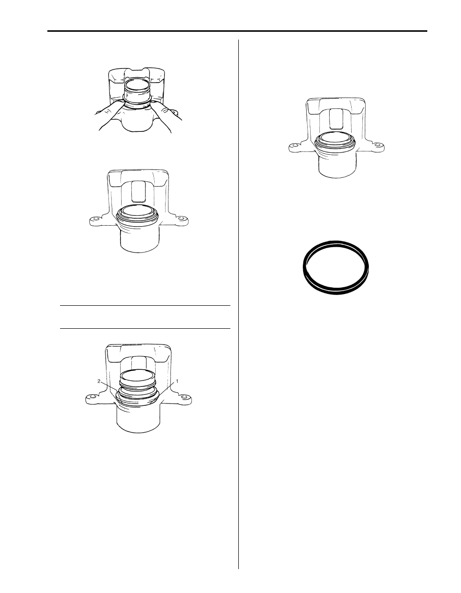
2) Fit boot as it is in above figure into boot groove in
cylinder with fingers.
3) Insert piston into cylinder by hand and fit boot in boot
groove in piston.
4) To confirm that boot is fitted in its groove in cylinder
properly, pull piston out of cylinder a little but do not
take it all out.
NOTE
Boot’s face (1) should be at the same level
from cylinder’s face (2) all around.
5) Install piston into cylinder by hand.
Caliper
Before installing caliper (cylinder body) to carrier, check
to ensure that guide pin (pin bolt) inserted in each caliper
carrier hole can be moved smoothly in thrust direction.
Front Disc Brake Caliper Inspection
S6JB0B4206007
Cylinder Boot
Check boots for breakage, crack and damage. If
defective, replace.
Piston Seal
Excessive or uneven wear of pad lining may indicate
unsmooth return of the piston. In such a case, replace
rubber seal.
I2RH01420019-01
I2RH01420020-01
I4RS0A420004-01
IYSQ01420022-01
IYSQ01420023-01
Нет комментариевНе стесняйтесь поделиться с нами вашим ценным мнением.
Текст