Suzuki Grand Vitara JB627. Manual — part 434
10E-21 Keyless Start System:
No DTC Detection After Performing DTC Check
S6JB0BA504014
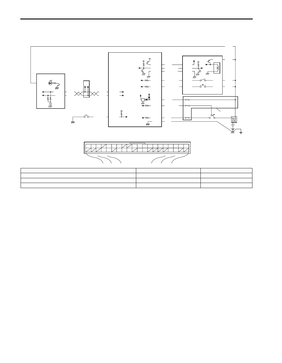
Wiring Diagram
BLK
G44-9
G44-15
G44-14
G44-16
G44-20
G44-29
G44-30
G44-10
G44-34
G44-11
WHT/BLK
WHT
WHT
RED/BLK
YEL
5V
5V
5V
5V
5V
12V
12V
WHT
RED
WHT
RED
G44-18
G44-19
BLU/RED
BRN/RED
BLK/YEL
BRN/YEL
ORN
G22-3
G22-4
G22-5
G22-2
G22-1
G22-6
G22-7
G22-8
WHT
WHT
G44
[A]
[B]
1
2
3
4
5
6
7
8
9
10
11
14
15
16
36
34 33 32
30 29
24 23
37
18
19
20
WHT
G28-8
G28-10
G28-14
7
10
1
2
4
9
5
3
6
8
I6JB01A50005-01
[A]: Keyless start control module connector (viewed from harness side)
3. Steering lock solenoid
7. Combination meter
[B]: To each control module
4. Ignition knob switch
8. Key indicator light
1. Keyless start control module
5. Key reminder switch
9. Junction box
2. Steering lock unit
6. Driver side door request switch
10. Junction connector

Keyless Start System: 10E-22
Description
The keyless start control module detects DTC by using signals from the key reminder and driver side door request
switches. The keyless start control module makes the key indicator light in the combination meter flash on and off by
using CAN communication.
Troubleshooting
Step
Action
Yes
No
1
Combination meter power and ground circuit check
1) Turn ignition switch to ON position.
Do warning light in combination meter other than key
indicator light light up?
Go to Step 2.
Check main fuse, circuit
fuse, combination meter
power and ground
circuit.
2
Driver side door request switch and its circuit check
1) Check driver side door request switch and its circuit
Is it in good condition?
Go to Step 3.
Repair or replace
malfunction part.
3
Key reminder switch and its circuit check
1) Turn ignition switch to OFF position.
2) Disconnect connector from ignition switch.
3) Check key reminder switch for operation referring to
“Ignition Switch Inspection in Section 9C”.
4) If OK, check for open, short and high resistance in key
reminder switch circuit.
Is it in good condition?
Go to Step 4.
Repair or replace
malfunction part.
4
Keyless start control module power supply and ground
circuit
1) Check keyless start control module power and ground
circuit for condition referring to “Keyless Start Control
Module Power and Ground Circuit Check”.
Is it in good condition?
Go to Step 5.
Repair circuit.
5
CAN communication circuit check
1) Turn ignition switch to OFF position.
2) Disconnect connectors of all control modules
communicating by means of CAN.
3) Check CAN communication circuit between control
modules for open, short and high resistance.
Is each CAN communication circuit in good condition?
Substitute a known-
good keyless start
control module and
recheck.
Repair circuit.
10E-23 Keyless Start System:
Key Indicator Light Circuit Check (Key Indicator Light Doesn’t Light when Ignition Knob Switch is
Pushed)
S6JB0BA504015
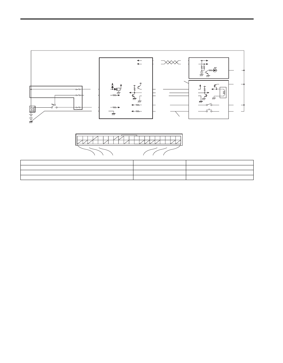
Wiring Diagram
Description
When the ignition knob switch is pushed, the key indicator light lights up in blue if you carry the remote controller
registered in the keyless start control module and it lights in red if you carry the remote controller which has not been
registered in the keyless start control module or if you carry no remote controller.
BLK G44-9
G44-15
G44-14
G44-20
G44-29
G44-30
G44-10
G44-34
G44-11
WHT/BLK
WHT
WHT
YEL
5V
5V
5V
5V
5V
12V
WHT
RED
WHT
RED
G44-18
G44-19
BLU/RED
BRN/RED
BLK/YEL
BRN/YEL
ORN
G22-3
G22-4
G22-5
G22-2
G22-1
G22-6
G22-7
G22-8
WHT
WHT
G44
[A]
1
2
3
4
5
6
7
8
9
10
11
14
15
16
36
34 33 32
30 29
24 23
37
18
19
20
WHT
G28-8
G28-10
G28-14
8
1
2
3
5
7
6
4
9
I7JB01A50002-01
[A]: Keyless start control module connector (viewed from harness side)
4. Steering lock unit
8. Junction block
1. Keyless start control module
5. Steering lock solenoid
9. Ignition knob switch signal circuit
2. Combination meter
6. Key reminder switch
3. Key indicator light
7. Ignition knob switch

Keyless Start System: 10E-24
Troubleshooting
Step
Action
Yes
No
1
Combination meter power and ground circuit check
1) Turn ignition switch to ON position.
Do warning light in combination meter other than key
indicator light light up?
Go to Step 2.
Check main fuse, circuit
fuse, combination meter
power and ground
circuit.
2
Keyless start control module power and ground circuit
check
1) Check keyless start control module power and ground
circuit for condition referring to “Keyless Start Control
Module Power and Ground Circuit Check”.
Is it in good condition?
Go to Step 3.
Repair circuit.
3
Steering lock unit ignition knob switch check
1) Check ignition knob switch of steering lock unit for
operation referring to “Steering Lock Unit Inspection”.
Is it in good condition?
Go to Step 4.
Replace steering lock
unit.
4
Wire harness check
1) Turn ignition switch to OFF position.
2) Disconnect connector from keyless start control module,
steering lock unit and combination meter.
3) Check for open, short and high resistance in following
circuits.
• Ignition knob switch signal circuit
• Keyless start control module and combination meter
CAN communication circuit
Is it in good condition?
Go to Step 5.
Repair circuit.
5
Keyless start system operation check
1) With remote controller of which ID code is registered in
keyless start control module carried with you, try to turn
ignition knob switch.
Can it be turned to any position other than “LOCK” position?
Replace combination
meter.
Substitute a known-
good keyless start
control module and
recheck.
Нет комментариевНе стесняйтесь поделиться с нами вашим ценным мнением.
Текст