Suzuki Grand Vitara JB627. Manual — part 58

1A-181 Engine General Information and Diagnosis:
DTC Troubleshooting
NOTE
Before this trouble shooting is performed, read the precautions for DTC troubleshooting referring to
“Precautions for DTC Troubleshooting”.
Step
Action
Yes
No
1
Was “Engine and Emission Control System Check”
performed?
Go to Step 2.
Go to “Engine and
Emission Control
System Check”.
2
A/F sensor adjusting resistor circuit check
1) Disconnect connectors from A/F sensor (bank-2) and
ECM with ignition switch turned OFF.
2) Check for proper terminal connection to A/F sensor
(bank-2) connector and ECM connector.
3) If connections are OK, check that A/F sensor (bank-2)
adjusting resistor circuit is as follows.
• Wiring harness resistance of each “Adjusting resistor
(+) circuit of A/F sensor (bank-2)” and “Adjusting
resistor (–) circuit of A/F sensor (bank-2)” is less than
1
Ω.
• Insulation resistance between “Adjusting resistor (+)
circuit of A/F sensor (bank-2)” and vehicle body
ground is infinity.
• Insulation resistance between “Adjusting resistor (+)
circuit of A/F sensor (bank-2)” and “Adjusting resistor
(–) circuit of A/F sensor (bank-2)” is infinity.
• Insulation resistance of wire harness is infinity
between “Signal (+) circuit of A/F sensor (bank-2)”
terminal and each other terminal at A/F sensor (bank-
2) connector.
• Insulation resistance of wire harness is infinity
between “Signal (–) circuit of A/F sensor (bank-2)”
terminal and each other terminal at A/F sensor (bank-
2) connector.
• Circuit voltage between “Adjusting resistor (+) circuit
of A/F sensor (bank-2)” and vehicle body ground is 0
V with ignition switch tuned ON.
Are they in good condition?
Go to Step 3.
Repair or replace
defective wiring
harness.
3
A/F sensor adjusting resistor check
1) Check for resistance of A/F sensor (bank-2) adjusting
resistor referring to “Air Fuel Ratio (A/F) Sensor On-
Vehicle Inspection in Section 1C”.
Is check result satisfactory?
Substitute a known
good ECM and recheck.
If ECM OK, replace A/F
sensor (bank-2).
Replace A/F sensor
(bank-2).
Engine General Information and Diagnosis: 1A-182
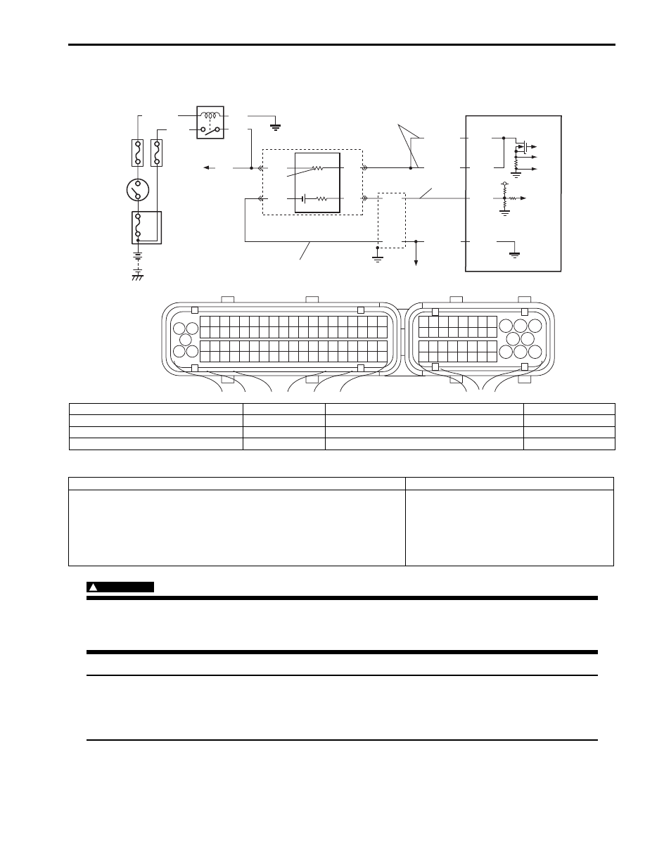
DTC P2A01: O2 Sensor Circuit Performance (Sensor-2, Bank-1)
S6JB0B1104078
Wiring Diagram
DTC Detecting Condition and Trouble Area
WARNING
!
• When performing a road test, select a place where there is no traffic or possibility of a traffic
accident and be very careful during testing to avoid occurrence of an accident.
• Road test should be carried out by 2 persons, a driver and a tester, on a level road.
NOTE
Check to make sure that following conditions are satisfied when using this “DTC Confirmation
Procedure”.
• Engine coolant temperature: 70
°C (158 °F) or more.
• The following DTCs are not detected: A/F sensor, A/F sensor heater and HO2S heater.
4
3
9
RED
GRN
PNK
BLK
C37-2
C37-3
C37-67
6
2
7
10
BLK
BLU
WHT
BLK/RED
GRY/GRN
1
8
5
5V
BLK/WHT
BLK
PNK
GRN
C37-1
BLK/RED
1
3 2
4
5
6
7
8
9
1110
12
13
14
15
16
17
18
19
20
17
18
19
20
21
22
23
24
25
26
27
28
29
30
31
33
34
35
36
37
38
39
40
32
1
2
3
4
5
6
7
8
9
10
11
12
13
14
15
16
21
22
23
24
25
26
27
28
29
30
31
32
33
34
35
36
37
38
39
40
41
42
43
44
45
46
47
48
49
50
51
52
53
54
55
56
57
58
59
60
61
62
63
64
65
66
67
68
69
70
71
72
73
74
75
76
77
78
79
80
81
b
a
c
I6JB01110055-01
a. Signal circuit of HO2S (bank-1)
2. Shield wire
6. HO2S (bank-1)
10. To other sensors
b. Ground circuit of HO2S (bank-1)
3. Ignition Switch
7. HO2S heater
c. Control circuit of HO2S (bank-1) heater
4. O2 HTR fuse
8. To A/F sensor (bank-1 and -2), HO2S (bank-2)
1. HO2S heater relay
5. IG COIL fuse
9. ECM
DTC detecting condition
Trouble area
Circuit voltage of HO2S (bank-1) signal is less than 0.35 V while A/F
(fuel trim) is shifted rich to lean and lean to rich with specified diagnosis
frequency under specified running or Circuit voltage of HO2S (bank-1)
signal is more than 0.2 V for more than 4 sec. even though vehicle is
running with fuel cut mode below 4000 rpm.
(2 driving cycle detection logic, monitoring once per driving cycle)
• HO2S circuit
• HO2S
• ECM

1A-183 Engine General Information and Diagnosis:
1) With ignition switch turned OFF, connect scan tool.
2) Turn ON ignition switch and clear DTC using scan tool.
3) Start engine and warm up to normal operating temperature.
4) Drive vehicle at 40 mph (60 km/h) or higher. (engine speed: 2500 – 3000 r/min.)
5) Keep above vehicle speed for 6 min. or more. (Throttle valve opening is kept constant in this step.)
6) Release accelerator pedal and with engine brake applied, keep vehicle coasting (with fuel cut for 5 sec. or more)
and then stop vehicle.
7) Check if DTC and pending DTC exist by using scan tool. If not, check if oxygen sensor monitoring test has been
completed by using scan tool. If not in both of above checks (i.e., no DTC and pending DTC and oxygen sensor
monitoring test not completed), check vehicle condition (environmental) and repeat Step 3) through 6).
DTC Troubleshooting
NOTE
Before this trouble shooting is performed, read the precautions for DTC troubleshooting referring to
“Precautions for DTC Troubleshooting”.
Step
Action
Yes
No
1
Was “Engine and Emission Control System Check”
performed?
Go to Step 2.
Go to “Engine and
Emission Control
System Check”.
2
DTC check
Is there DTC P0140?
Go to applicable
DTC(s).
Go to Step 4.
3
DTC check
Is there DTC(s) other than P0140 and P2A01?
Go to applicable
DTC(s).
Go to Step 4.
4
Exhaust system for leakage check
1) Check exhaust system for leakage.
Is it in good condition?
Go to Step 5.
repair or replace
defective parts.
5
HO2S circuit check
1) Disconnect connector from HO2S (bank-1) and ECM
with ignition switch turned OFF.
2) Check for proper terminal connection to HO2S (bank-1)
connector and ECM connector.
3) If connections are OK, check that HO2S (bank-1) circuit
is as follows.
• Wiring harness resistance of each “Signal circuit of
HO2S (bank-1)”, “Ground circuit of HO2S (bank-1)”
and “Control circuit of HO2S (bank-1) heater” is less
than 1
Ω.
• Insulation resistance between “Signal circuit of HO2S
(bank-1)” and vehicle body ground is infinity.
• Insulation resistance of wire harness is infinity
between “Signal circuit of HO2S (bank-1)” terminal
and each other terminal at HO2S (bank-1) connector.
• Circuit voltage between “Signal circuit of HO2S (bank-
1)” and vehicle body ground is 0 V with ignition switch
turned ON.
Is it in good condition?
Replace HO2S (bank-
1).
Repair or replace
defective wiring
harness.
Engine General Information and Diagnosis: 1A-184
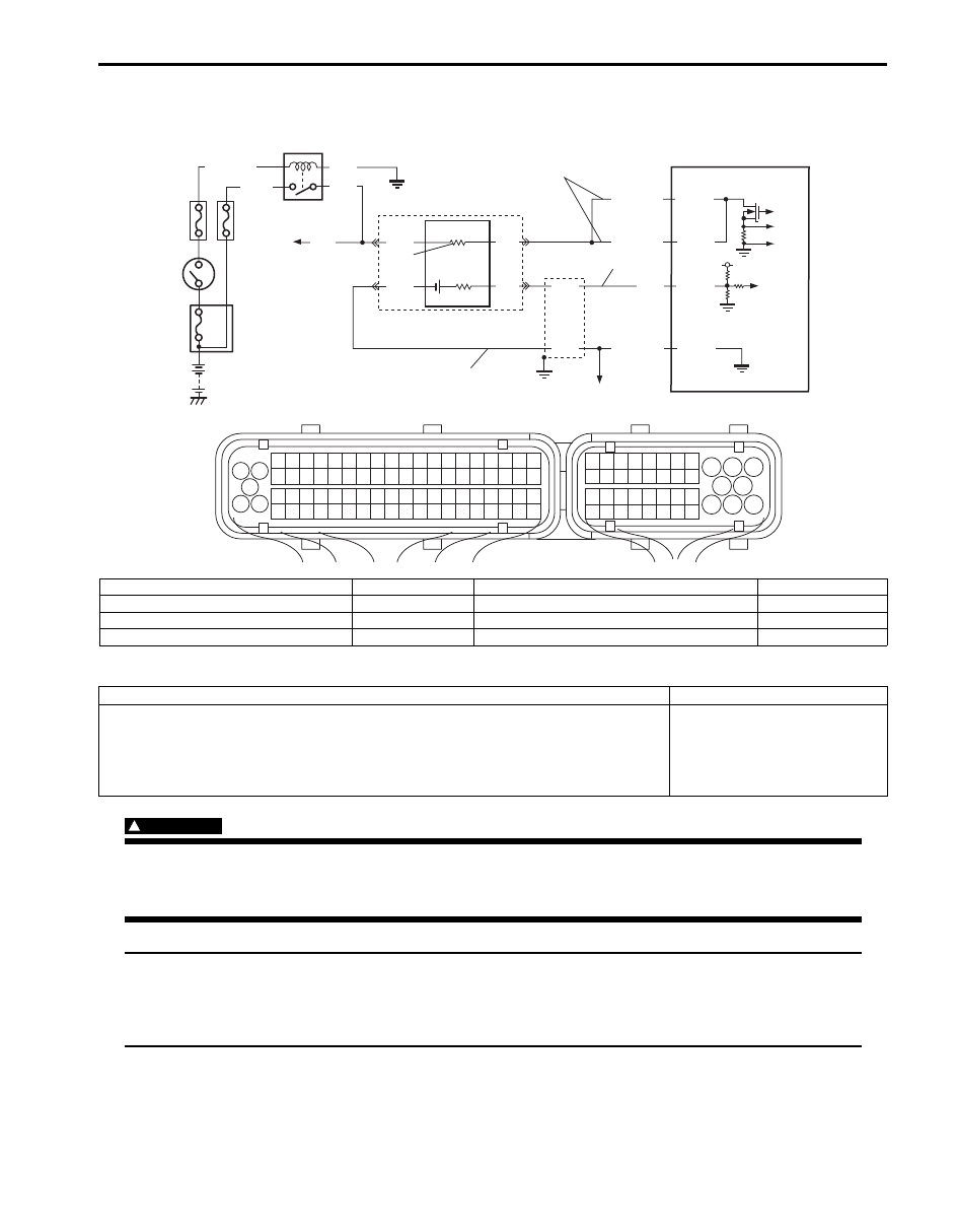
DTC P2A04: O2 Sensor Circuit Performance (Sensor-2, Bank-2)
S6JB0B1104079
Wiring Diagram
DTC Detecting Condition and Trouble Area
WARNING
!
• When performing a road test, select a place where there is no traffic or possibility of a traffic
accident and be very careful during testing to avoid occurrence of an accident.
• Road test should be carried out by 2 persons, a driver and a tester, on a level road.
NOTE
Check to make sure that following conditions are satisfied when using this “DTC Confirmation
Procedure”.
• Engine coolant temperature: 70
°C (158 °F) or more.
• The following DTCs are not detected: A/F sensor heater and HO2S heater.
4
3
9
RED
GRN
PNK
BLK
C37-21
C37-22
C37-67
6
2
7
10
BLK
BLU
WHT
WHT/BLK
GRY/GRN
1
8
5
5V
BLK/WHT
BLK
PNK
GRN
C37-20
WHT/BLK
1
3 2
4
5
6
7
8
9
1110
12
13
14
15
16
17
18
19
20
17
18
19
20
21
22
23
24
25
26
27
28
29
30
31
33
34
35
36
37
38
39
40
32
1
2
3
4
5
6
7
8
9
10
11
12
13
14
15
16
21
22
23
24
25
26
27
28
29
30
31
32
33
34
35
36
37
38
39
40
41
42
43
44
45
46
47
48
49
50
51
52
53
54
55
56
57
58
59
60
61
62
63
64
65
66
67
68
69
70
71
72
73
74
75
76
77
78
79
80
81
RED
c
a
b
I6JB01110097-01
a. Signal circuit of HO2S (bank-2)
2. Shield wire
6. HO2S (bank-2)
10. To other sensors
b. Ground circuit of HO2S (bank-2)
3. Ignition switch
7. HO2S heater
c. Control circuit of HO2S (bank-2) heater
4. O2 HTR fuse
8. To A/F sensor (bank-1 and -2), HO2S (bank-1)
1. HO2S heater relay
5. IG COIL fuse
9. ECM
DTC detecting condition
Trouble area
Circuit voltage of HO2S (bank-2) signal is less than 0.35 V while A/F (fuel trim) is
shifted rich to lean and lean to rich with specified diagnosis frequency under
specified running or Circuit voltage of HO2S (bank-2) signal is more than 0.2 V for
more than 4 sec. even though vehicle is running with fuel cut mode below 4000 rpm.
(2 driving cycle detection logic, monitoring once per driving cycle)
• HO2S circuit
• HO2S
• ECM
Нет комментариевНе стесняйтесь поделиться с нами вашим ценным мнением.
Текст