Suzuki Grand Vitara JB627. Manual — part 57

1A-177 Engine General Information and Diagnosis:
DTC Troubleshooting
NOTE
Before this trouble shooting is performed, read the precautions for DTC troubleshooting referring to
“Precautions for DTC Troubleshooting”.
Step
Action
Yes
No
1
Was “Engine and Emission Control System Check”
performed?
Go to Step 2.
Go to “Engine and
Emission Control
System Check”.
2
A/F sensor signal check
1) Connect scan tool with ignition switch turned OFF.
2) Warm up engine to normal operating temperature and
keep it at 2000 r/min. for 60 sec.
3) Repeat racing engine (Repeat depressing accelerator
pedal 5 to 6 times continuously to enrich A/F mixture and
take foot off from pedal to enlean it).
4) Check for A/F sensor (bank-2) output current displayed
on scan tool.
Does A/F sensor output current between –0.2 mA and 0.2
mA?
Intermittent trouble.
Check for intermittent
referring to “Intermittent
and Poor Connection
Inspection in Section
00”.
Go to Step 3.
3
A/F sensor circuit check
1) Disconnect connector from A/F sensor (bank-2) and
ECM with ignition switch turned OFF.
2) Check for proper terminal connection to A/F sensor
(bank-2) connector and ECM connector.
3) If connections are OK, check that A/F sensor (bank-2)
circuit is as follows.
• Wiring harness resistance of each “Signal (+) circuit of
A/F sensor (bank-2)”, “Signal (–) circuit of A/F sensor
(bank-2)” is less than 1
Ω.
• Insulation resistance between “Signal (–) circuit of A/F
sensor (bank-2)” and vehicle body ground is infinity.
• Insulation resistance between “Signal (+) circuit of A/F
sensor (bank-2)” and “Signal (–) circuit of A/F sensor
(bank-2)” is infinity.
• Insulation resistance of wire harness is infinity
between “Signal (+) circuit of A/F sensor (bank-2)”
terminal and each other terminal at A/F sensor (bank-
2) connector.
• Insulation resistance of wire harness is infinity
between “Signal (–) circuit of A/F sensor (bank-2)”
terminal and each other terminal at A/F sensor (bank-
2) connector.
• Circuit voltage between “Signal (–) circuit of A/F
sensor (bank-2)” and vehicle body ground is 0 V with
ignition switch tuned ON.
Are they in good condition?
Go to Step 4.
Repair or replace
defective wiring
harness.
4
A/F sensor heater check
1) Check A/F sensor (bank-2) referring to “Air Fuel Ratio
(A/F) Sensor On-Vehicle Inspection in Section 1C”.
Is A/F sensor in good condition?
Substitute a known
good ECM and recheck.
If ECM OK, replace A/F
sensor (bank-2).
Replace A/F sensor
(bank-2).
Engine General Information and Diagnosis: 1A-178
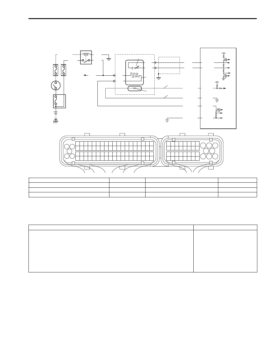
DTC P2627 / P2628: O2 Sensor Pumping Current Trim Circuit Low / High (Sensor-1, Bank-1)
S6JB0B1104076
System and Wiring Diagram
A/F Sensor Description
Refer to “A/F Sensor Description”
DTC Detecting Condition and Trouble Area
DTC Confirmation Procedure
1) With ignition switch turned OFF, connect scan tool to DLC.
2) Turn ON ignition switch and clear DTC.
3) Start engine and warm up to normal operating temperature.
4) Run engine at idle speed for 1 min. or more.
5) Check DTC and pending DTC.
4
3
9
PNK
6
2
1
a
b
8
5
BLK/WHT
BLK
PNK
GRN
C37-16
C37-77
C37-19
C37-18
BLK
BLK
BLU
WHT
C37-17
C37-79
BLK
WHT
RED/YEL
RED/BLU
PNK/BLK
BLK/YEL
10
7
11
5 V
5 V
1
3 2
4
5
6
7
8
9
1110
12
13
14
15
16
17
18
19
20
17
18
19
20
21
22
23
24
25
26
27
28
29
30
31
33
34
35
36
37
38
39
40
32
1
2
3
4
5
6
7
8
9
10
11
12
13
14
15
16
21
22
23
24
25
26
27
28
29
30
31
32
33
34
35
36
37
38
39
40
41
42
43
44
45
46
47
48
49
50
51
52
53
54
55
56
57
58
59
60
61
62
63
64
65
66
67
68
69
70
71
72
73
74
75
76
77
78
79
80
81
I6JB01110106-01
a. Adjusting resistor (+) circuit of A/F sensor (bank-1)
3. Ignition Switch
7. A/F sensor heater
11. A/F sensor element
b. Adjusting resistor (–) circuit of A/F sensor (bank-1)
4. O2 HTR fuse
8. To A/F sensor (bank-2), HO2S (bank-1 and-2)
1. HO2S heater relay
5. IG COIL fuse
9. ECM
2. Shield wire
6. A/F sensor
10. Adjusting resistor (if equipped)
DTC detecting condition
Trouble area
DTC P2627 O2 Sensor Pumping Current Trim Circuit Low (Sensor-1, Bank-1):
Output voltage of A/F sensor adjusting resister is less than 0.1 V for more than 4 sec.
continuously with engine running.
(1 driving cycle detection logic)
DTC P2628 O2 Sensor Pumping Current Trim Circuit High (Sensor-1, Bank-1):
Output voltage of A/F sensor adjusting resister is more than 5 V for more than 4 sec.
continuously with engine running.
(1 driving cycle detection logic)
• A/F sensor malfunction
• A/F sensor circuit malfunction
• ECM

1A-179 Engine General Information and Diagnosis:
DTC Troubleshooting
NOTE
Before this trouble shooting is performed, read the precautions for DTC troubleshooting referring to
“Precautions for DTC Troubleshooting”.
Step
Action
Yes
No
1
Was “Engine and Emission Control System Check”
performed?
Go to Step 2.
Go to “Engine and
Emission Control
System Check”.
2
A/F sensor adjusting resistor circuit check
1) Disconnect connectors from A/F sensor (bank-1) and
ECM with ignition switch turned OFF.
2) Check for proper terminal connection to A/F sensor
(bank-1) connector and ECM connector.
3) If connections are OK, check that A/F sensor (bank-1)
adjusting resistor circuit is as follows.
• Wiring harness resistance of each “Adjusting resistor
(+) circuit of A/F sensor (bank-1)” and “Adjusting
resistor (–) circuit of A/F sensor (bank-1)” is less than
1
Ω.
• Insulation resistance between “Adjusting resistor (+)
circuit of A/F sensor (bank-1)” and vehicle body
ground is infinity.
• Insulation resistance between “Adjusting resistor (+)
circuit of A/F sensor (bank-1)” and “Adjusting resistor
(–) circuit of A/F sensor (bank-1)” is infinity.
• Insulation resistance of wire harness is infinity
between “Signal (+) circuit of A/F sensor (bank-1)”
terminal and each other terminal at A/F sensor (bank-
1) connector.
• Insulation resistance of wire harness is infinity
between “Signal (–) circuit of A/F sensor (bank-1)”
terminal and each other terminal at A/F sensor (bank-
1) connector.
• Circuit voltage between “Adjusting resistor (+) circuit
of A/F sensor (bank-1)” and vehicle body ground is 0
V with ignition switch tuned ON.
Are they in good condition?
Go to Step 3.
Repair or replace
defective wiring
harness.
3
A/F sensor adjusting resistor check
1) Check heater resistance of A/F sensor (bank-1)
adjusting resistor referring to “Air Fuel Ratio (A/F)
Sensor On-Vehicle Inspection in Section 1C”.
Is check result satisfactory?
Substitute a known
good ECM and recheck.
If ECM OK, replace A/F
sensor (bank-1).
Replace A/F sensor
(bank-1).
Engine General Information and Diagnosis: 1A-180
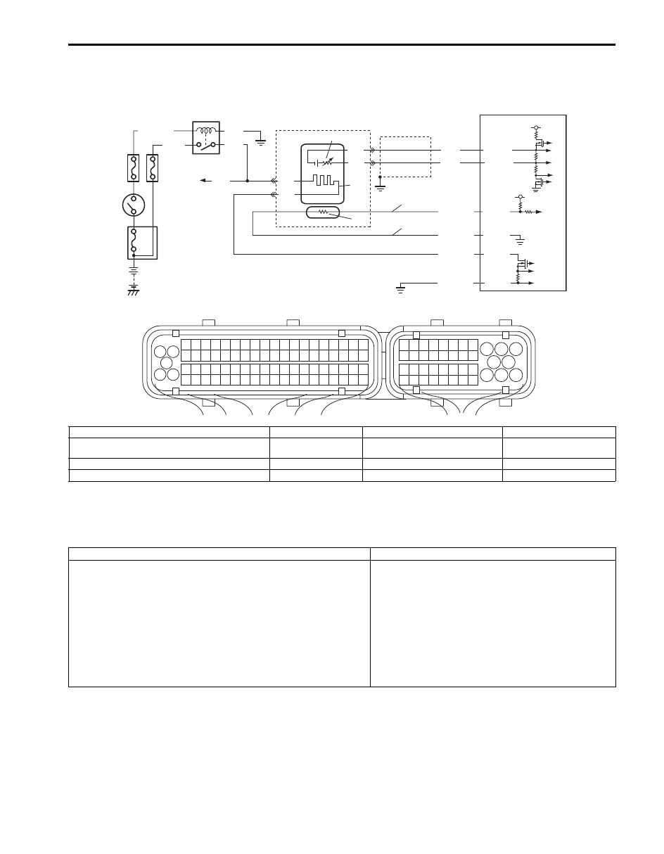
DTC P2630 / P2631: O2 Sensor Pumping Current Trim Circuit Low / High (Sensor-1, Bank-2)
S6JB0B1104077
System and Wiring Diagram
A/F Sensor Description
Refer to “A/F Sensor Description”
DTC Detecting Condition and Trouble Area
DTC Confirmation Procedure
1) With ignition switch turned OFF, connect scan tool to DLC.
2) Turn ON ignition switch and clear DTC.
3) Start engine and warm up to normal operating temperature.
4) Run engine at idle speed for 1 min. or more.
5) Check DTC and pending DTC.
4
3
9
PNK
6
2
1
8
5
BLK/WHT
BLK
PNK
GRN
C37-35
C37-78
C37-38
C37-37
BLK
BLK
BLU
WHT
C37-36
C37-79
BRN
YEL
BLU/YEL
BLU/RED
PNK/BLU
BLK/YEL
10
7
11
5 V
5 V
1
3 2
4
5
6
7
8
9
1110
12
13
14
15
16
17
18
19
20
17
18
19
20
21
22
23
24
25
26
27
28
29
30
31
33
34
35
36
37
38
39
40
32
1
2
3
4
5
6
7
8
9
10
11
12
13
14
15
16
21
22
23
24
25
26
27
28
29
30
31
32
33
34
35
36
37
38
39
40
41
42
43
44
45
46
47
48
49
50
51
52
53
54
55
56
57
58
59
60
61
62
63
64
65
66
67
68
69
70
71
72
73
74
75
76
77
78
79
80
81
a
b
I6JB01110107-01
a. Adjusting resistor (+) circuit of A/F sensor (bank-1)
3. Ignition Switch
7. A/F sensor heater
11. A/F sensor element
b. Adjusting resistor (–) circuit of A/F sensor (bank-1)
4. O2 HTR fuse
8. To A/F sensor (bank-1), HO2S
(bank-1 and -2)
1. HO2S heater relay
5. IG COIL fuse
9. ECM
2. Shield wire
6. A/F sensor
10. Adjusting resistor (if equipped)
DTC detecting condition
Trouble area
DTC P2630 O2 Sensor Pumping Current Trim Circuit Low
(Sensor-1, Bank-2):
Output voltage of A/F sensor adjusting resister is less than 0.1 V
for more than 4 sec. continuously with engine running.
(1 driving cycle detection logic)
DTC P2631 O2 Sensor Pumping Current Trim Circuit High
(Sensor-1, Bank-2):
Output voltage of A/F sensor adjusting resister is more than 5 V
for more than 4 sec. continuously with engine running.
(1 driving cycle detection logic)
• A/F sensor malfunction
• A/F sensor circuit malfunction
• ECM
Нет комментариевНе стесняйтесь поделиться с нами вашим ценным мнением.
Текст