Suzuki Grand Vitara JB627. Manual — part 96
1D-65 Engine Mechanical:
Main Bearings, Crankshaft and Cylinder Block
Removal and Installation
S6JB0B1406044
Removal
1) Remove engine assembly from vehicle referring to
“Engine Assembly Removal and Installation”.
2) Remove clutch and flywheel (for M/T vehicle) or
drive plate (for A/T vehicle). For clutch removal, refer
to “Clutch Cover, Clutch Disc and Flywheel Removal
and Installation in Section 5C”.
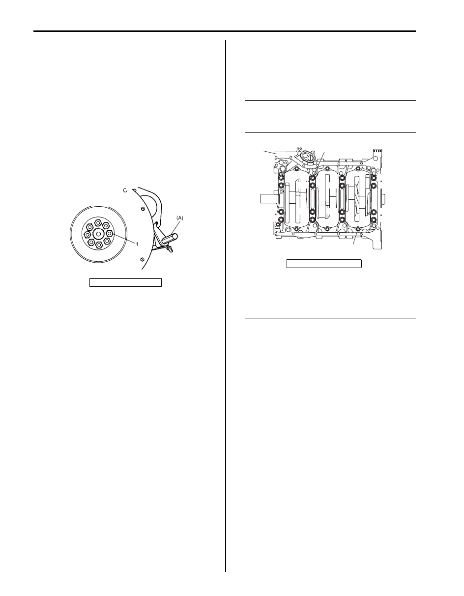
Using special tool (flywheel holder), remove flywheel
(M/T vehicle) or drive plate (A/T vehicle).
Special tool
(A): 09924–17811
3) Remove electric throttle body assembly with intake
collector and intake manifold.
4) Remove oil pans (lower and upper) and oil pump
strainer. Refer to “Oil Pan and Oil Pump Strainer
Removal and Installation in Section 1E”.
5) Remove cylinder head cover referring to “Cylinder
Head Covers Removal and Installation”.
6) Remove timing chain cover. Refer to “Timing Chain
Cover Removal and Installation”.
7) Remove LH (No.1) bank 2nd timing chain and
tensioner referring to “LH (No.1) Bank 2nd Timing
Chain and Chain Tensioner Removal and
Installation”.
8) Remove 1st timing chain and tensioner referring to
“1st Timing Chain and Chain Tensioner Removal and
Installation”.
9) Remove RH (No.2) bank 2nd timing chain and
tensioner referring to “RH (No.2) Bank 2nd Timing
Chain and Chain Tensioner Removal and
Installation”.
10) Remove cylinder heads referring to “Valves and
Cylinder Heads Removal and Installation”.
11) Remove pistons and connecting rods referring to
“Pistons, Piston Rings, Connecting Rods and
Cylinders Removal and Installation”.
12) Remove oil pump referring to “Oil Pump and Oil
Pump Chain Removal and Installation in Section
1E”.
13) Remove oil pump chain referring to “Oil Pump and
Oil Pump Chain Removal and Installation in Section
1E”.
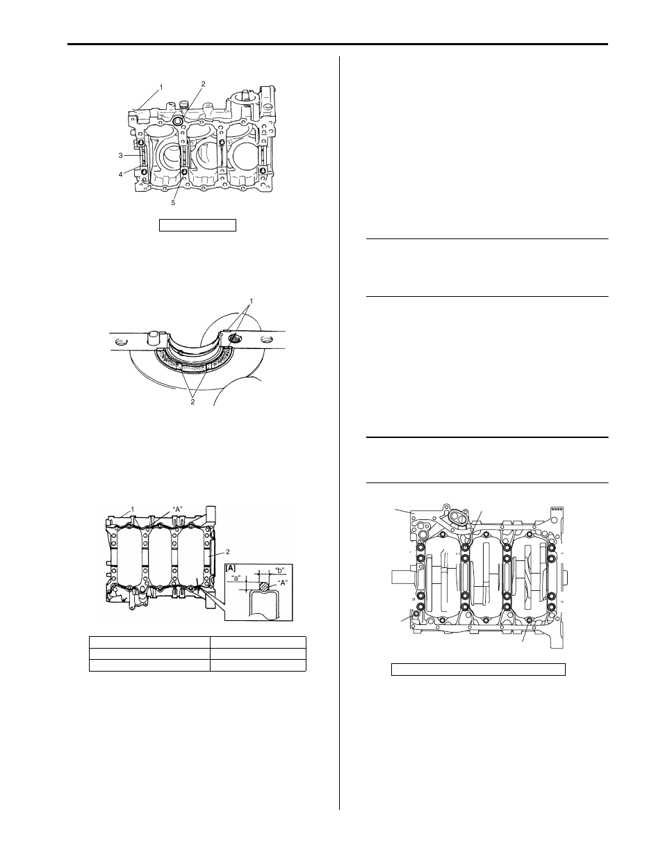
14) Loosen crankcase bolts by numerical order (“1”
through “17”) in figure and remove them.
NOTE
Loosen 8 mm (0.31 in.) thread diameter bolts
(2) first, then loosen 10 mm (0.39 in.) thread
diameter bolts (3).
15) Remove crankshaft from cylinder block.
Installation
NOTE
• All parts to be installed must be perfectly
clean.
• Be sure to apply oil crankshaft journals,
main bearings, thrust bearings, crank pins,
connecting rod bearings, pistons, piston
rings and cylinder bores.
• Main bearings, crankcase (bearings caps),
connecting rods, connecting rod bearings,
connecting rod bearing caps, pistons and
piston rings are in combination sets. Do
not disturb combination and try to see that
each part goes back to where it came from,
when installing.
• Clean mating surface of cylinder block and
crankcase, remove oil, old sealant and
dust from mating surface.
1) Fit main bearings (4) to cylinder block (1).
One of two halves of main bearing, has oil groove
(3). Install this half with oil groove to cylinder block,
and another half without oil groove to crankcase.
Make sure that two halves are painted in the same
color.
1. Flywheel bolt
IYSQ01143150-01
1. Lower crankcase
1
2
3,
“1”
“9”
“2”
“10”
“6”
“5”
“14”
“8”
“16”
“4”
“12”
“13”
“7”
“15”
“3”
“11”
“17”
I6JB01140103-01
Engine Mechanical: 1D-66
2) Install O-ring (2) to cylinder block.
3) Fit thrust bearings (1) to cylinder block between No.4
and No.5 cylinders.
Face oil groove (2) sides to crank webs.
4) Put crankshaft to cylinder block.
5) Apply sealant “A” to lower crankcase mating surface
area as shown in figure.
“A”: Sealant 99000–31260 (SUZUKI Bond
No.1217G)
6) Install lower crankcase (1) to cylinder block. Apply oil
to crankcase bolts before installing them. Tighten
crankcase bolts gradually as follows.
a) Tighten crankcase bolts (10 mm (0.39 in.) thread
diameter) (2) to 30 N
⋅m (3.0 kgf-m, 22.0 lb-ft)
according to numerical order in figure.
b) In the same manner as Step a), tighten them to
42 N
⋅m (4.2 kgf-m, 30.5 lb-ft).
c) In the same manner as Step a), retighten by
turning through 40
°.
d) Tighten crankcase bolts (8 mm (0.31 in.) thread
diameter) (3) to specified torque.
NOTE
Tighten 10 mm (0.39 in.) thread diameter
bolts first (the following the order shown in
figure), then tighten 8 mm (0.31 in.) thread
diameter bolts.
Tightening torque
Lower crankcase bolt (10 mm (0.39 in.) thread
diameter) (a): Tighten 30 N
⋅m (3.0 kgf-m,22.0
lb-ft), 0 N
⋅m (0 kgf-m, 0 lb-ft), 42 N⋅m (4.2 kgf-
m, 30.5 lb-ft) and 40
° by the specified
procedure
Lower crankcase bolt (8 mm (0.31 in.) thread
diameter) (b): 27 N
⋅m (2.7 kgf-m,19.5 lb-ft) by
the specified procedure
NOTE
After tightening crankcase bolts, check to be
sure that crankshaft rotates smoothly when
turned by hand.
5. Knock pin
[A]: Sealant application amount
1. Lower crankcase
“a”: 2 mm (0.08 in.)
2. Bearing
“b”: 3 mm (0.11 in.)
I2JA01143002-01
IYSQ01143153-01
I4JA01140026-02
4. Long bolt (8 mm (0.31 in.) thread diameter)
1
2, (a)
3, (b)
4, (b)
“1”
“9”
“2”
“10”
“6”
“14”
“8”
“16”
“4”
“12”
“5”
“13”
“7”
“15”
“3”
“11”
I6JB01140104-01
1D-67 Engine Mechanical:
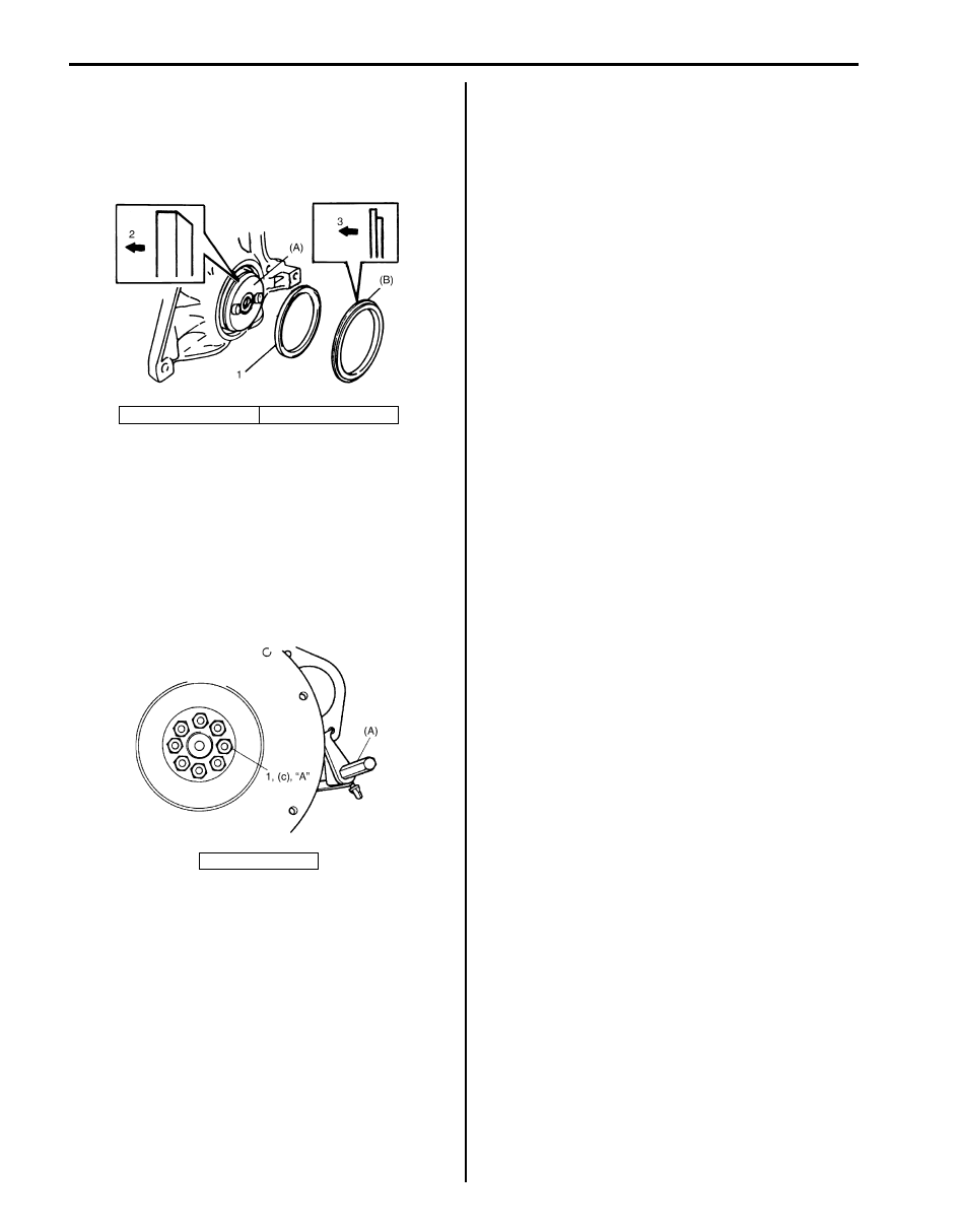
7) Using special tools (Oil seal installer and oil seal
guide), install rear oil seal (1).
Special tool
(A): 09911–97710
(B): 09911–97811
8) Install flywheel (M/T vehicle) or drive plate (A/T
vehicle). Using special tool, lock flywheel or drive
plate, and tighten new flywheel bolts or new drive
plate bolts to specification.
Special tool
(A): 09924–17811
Tightening torque
Flywheel (or drive plate) bolt (c): 70 N·m (7.0
kgf-m, 51.0 lb-ft)
9) Install oil pump referring to “Oil Pump and Oil Pump
Chain Removal and Installation in Section 1E”.
10) Install pistons and connecting rods referring to
“Pistons, Piston Rings, Connecting Rods and
Cylinders Removal and Installation”.
11) Install oil pump strainer and oil pans referring to “Oil
Pan and Oil Pump Strainer Removal and Installation
in Section 1E”.
12) Install cylinder heads assembly to cylinder block
referring to “Valves and Cylinder Heads Removal
and Installation”.
13) Install oil pump chain referring to “Oil Pump and Oil
Pump Chain Removal and Installation in Section
1E”.
14) Install RH (No.2) bank 2nd timing chain and
tensioner referring to “RH (No.2) Bank 2nd Timing
Chain and Chain Tensioner Removal and
Installation”.
15) Install 1st timing chain and tensioner referring to “1st
Timing Chain and Chain Tensioner Removal and
Installation”.
16) Install LH (No.1) bank 2nd timing chain and
tensioner referring to “LH (No.1) Bank 2nd Timing
Chain and Chain Tensioner Removal and
Installation”.
17) Install timing chain cover and crankshaft pulley
referring to “Timing Chain Cover Removal and
Installation”.
18) Install cylinder head covers referring to “Cylinder
Head Covers Removal and Installation”.
19) Install intake manifold, intake collector and electric
throttle body assembly referring to “Intake Collector
and Intake Manifold Removal and Installation” and
“Electric Throttle Body Assembly Removal and
Installation”.
20) Install clutch to flywheel (for M/T vehicle). For clutch
installation, refer to “Clutch Cover, Clutch Disc and
Flywheel Removal and Installation in Section 5C”.
21) Install engine assembly to vehicle referring to
“Engine Assembly Removal and Installation”.
2. Crankshaft side
3. Oil seal side
1. Flywheel bolt
I6JB01140105-01
I1SQ01143157-01
Engine Mechanical: 1D-68
Crankshaft Inspection
S6JB0B1406045
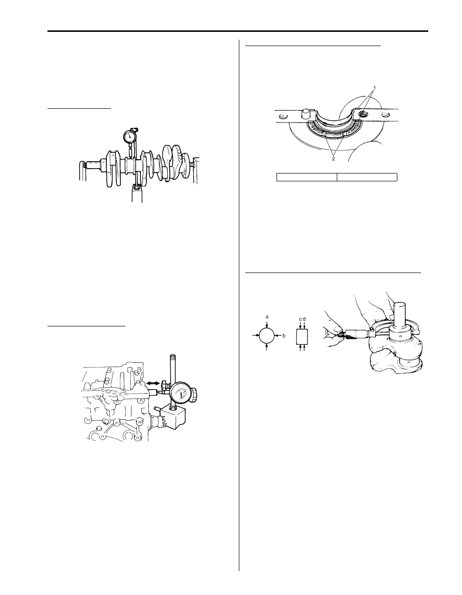
Crankshaft Runout
Using a dial gauge, measure runout at center journal.
Rotate crankshaft slowly. If runout exceeds its limit,
replace crankshaft.
Crankshaft runout
Limit: 0.06 mm (0.0023 in.)
Crankshaft Thrust Play
Measure this play with crankshaft set in cylinder block in
the normal manner, that is, with thrust bearing, lower
crankcase, main bearings and main bearing caps
installed. Refer to “Main Bearings, Crankshaft and
Cylinder Block Removal and Installation”.
Use a dial gauge to read displacement in axial (thrust)
direction of crankshaft.
If its limit is exceeded, replace thrust bearing with new
standard one or oversize one to obtain standard thrust
play.
Crankshaft thrust play
Standard: 0.10 – 0.35 mm (0.0040 – 0.0137 in.)
Limit: 0.38 mm (0.0150 in.)
Thickness of crankshaft thrust bearing
Standard: 2.425 – 2.475 mm (0.0955 – 0.0974 in.)
Oversize (0.125 mm): 2.488 – 2.538 mm (0.0980 –
0.0999 in.)
Out-of-Round and Taper (Uneven Wear) of Journals
An unevenly worn crankshaft journal shows up as a
difference in diameter at a cross section or along its
length (or both). This difference, if any, is determined by
taking micrometer readings. If any one of journals is
badly damaged or if amount of uneven wear in the sense
explained above exceeds its limit, regrind or replace
crankshaft.
Crank journal out-of-round (a – b) and taper (c – d)
Limit: 0.01 mm (0.0004 in.)
IYSQ01143158-01
IYSQ01143160-01
1. Thrust bearing
2. Oil groove
IYSQ01143153-01
IYSQ01143161-01
Нет комментариевНе стесняйтесь поделиться с нами вашим ценным мнением.
Текст