Suzuki Grand Vitara JB627. Manual — part 121
2A-1 Suspension General Diagnosis:
Suspension
Suspension General Diagnosis
Diagnostic Information and Procedures
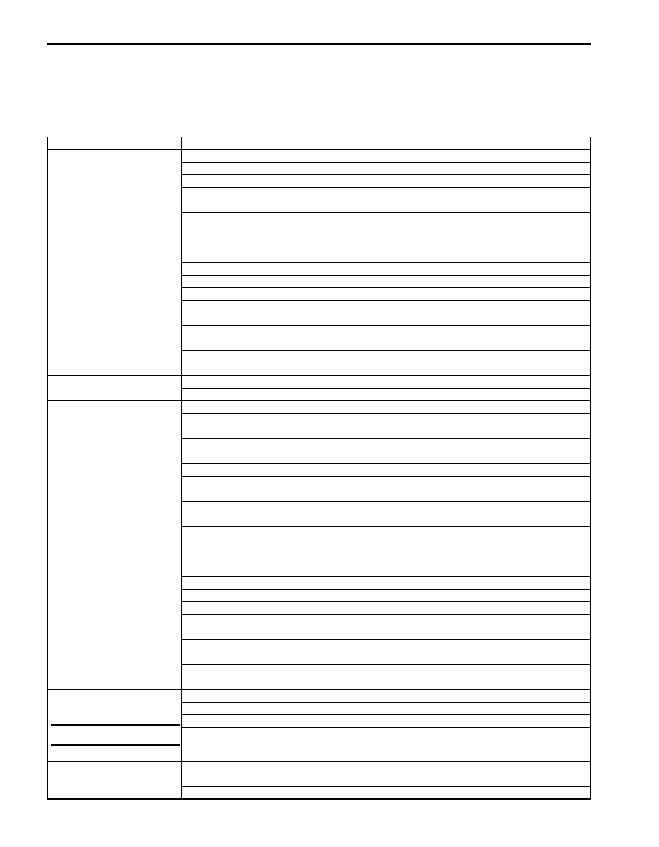
Suspension, Wheels and Tires Symptom Diagnosis
S6JB0B2104001
Condition
Possible cause
Correction / Reference Item
Vehicle pulls (Leads)
Mismatched or uneven tires
Replace tires.
Tires not adequately inflated
Adjust tire pressure.
Broken or sagging coil springs
Replace coil springs.
Radial tire lateral force
Replace tire.
Disturbed wheel alignment
Check and adjust wheel alignment.
Brake dragging in one road wheel
Repair brake.
Loose, bent or broken front or rear
suspension parts
Tighten or replace related suspension parts.
Abnormal or excessive
tire wear
Sagging or broken coil spring
Replace coil spring.
Tire out of balance
Adjust balance or replace tire.
Disturbed wheel alignment
Check and adjust wheel alignment.
Faulty strut (shock absorber)
Replace strut (shock absorber).
Hard driving
Replace tires.
Overloaded vehicle
Replace tires.
Not rotated tires
Replace or rotate tires.
Worn or loose wheel bearing
Replace wheel bearing.
Wobbly wheel or tire
Replace wheel or tire.
Tires not adequately inflated
Adjust tire pressure.
Wheel tramp
Blister or bump on tire
Replace tire.
Improper strut (shock absorber) action
Replace strut (shock absorber).
Shimmy, shake or
vibration
Tire or wheel out of balance
Balance wheel or replace tire and/or wheel.
Loosen wheel bearings
Replace wheel bearings.
Worn tie-rod ends
Replace tie-rod ends.
Worn lower ball joints
Replace front suspension control arm.
Excessive wheel runout
Repair or replace wheel and/or tire.
Blister or bump on tire
Replace tire.
Excessively loaded radial runout of tire /
wheel assembly
Replace tire or wheel.
Disturbed wheel alignment
Check and adjust wheel alignment.
Loose or worn steering linkage
Tighten or replace steering linkage.
Loose steering gear case bolts
Tighten steering gear case bolts.
Abnormal noise, front end Worn, sticky or loose tie-rod ends, lower
ball joints, tie-rod inside ball joints or
drive shaft joints
Replace tie-rod end, suspension arm, tie-rod
or drive shaft joint.
Damaged struts or mountings
Repair or replace struts or mountings.
Worn suspension arm bushings
Replace suspension arm bushings.
Loose stabilizer bar
Tighten bolts or nuts and/or replace bushes.
Loose wheel bolts
Tighten wheel bolts.
Loose suspension bolts or nuts
Tighten suspension bolts or nuts.
Broken or damaged wheel bearings
Replace wheel bearings.
Broken suspension springs
Replace suspension springs.
Poorly lubricated or worn strut bearings Replace strut bearing.
Malfunction of Power Steering System
Check and correct malfunction.
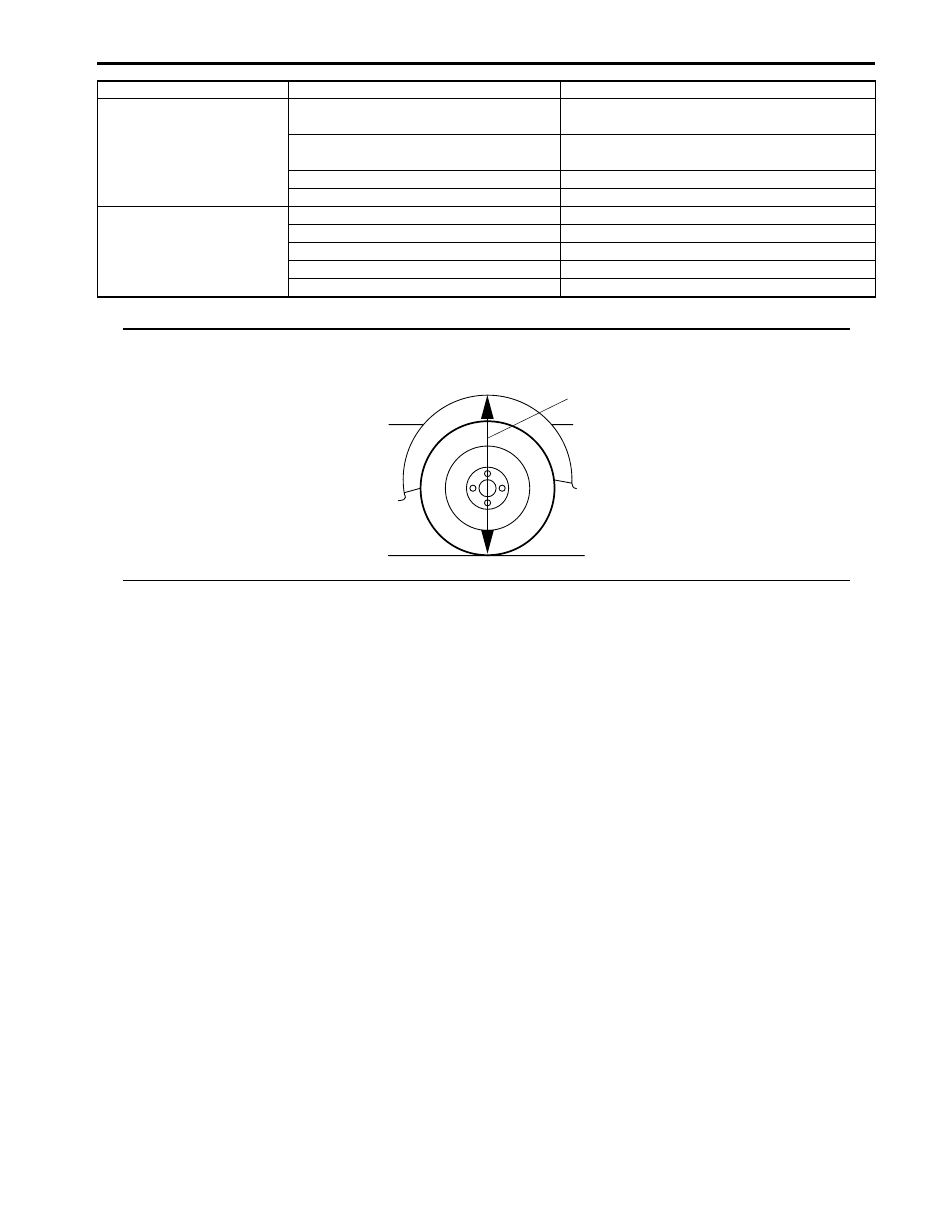
Low or uneven trim height
NOTE
See NOTE *1.
Broken or sagging coil springs
Replace coil springs.
Over loaded
Check loading.
Incorrect coil springs
Replace coil spring.
Tires not adequately inflated
Adjust tire pressure.
Ride too soft
Faulty strut (shock absorber)
Replace strut (shock absorber).
Suspension bottoms
Overloaded
Check loading.
Faulty strut (shock absorber)
Replace strut (shock absorber).
Incorrect, broken or sagging coil springs Replace coil spring.
Suspension General Diagnosis: 2A-2
NOTE
*1: Right-to-left trim height (“H”) difference should be within 15 mm (0.6 in.) with curb weight. (same
with rear side.)
Body leans or sways in
corners
Loose stabilizer bar
Tighten stabilizer bar bolts or nuts, or replace
bushes.
Faulty strut (shock absorber) or
mounting
Replace strut (shock absorber) or tighten
mounting.
Broken or sagging coil springs
Replace coil springs.
Overloaded
Check loading.
Cupped tires
Front struts defective
Replace struts.
Worn wheel bearings
Replace wheel bearings.
Excessive tire or wheel run-out
Replace tire and/or wheel.
Worn ball joints
Replace front suspension control arm.
Tire out of balance
Adjust tire balance.
Condition
Possible cause
Correction / Reference Item
“H”
I2RH01210001-01
2A-3 Suspension General Diagnosis:
Specifications
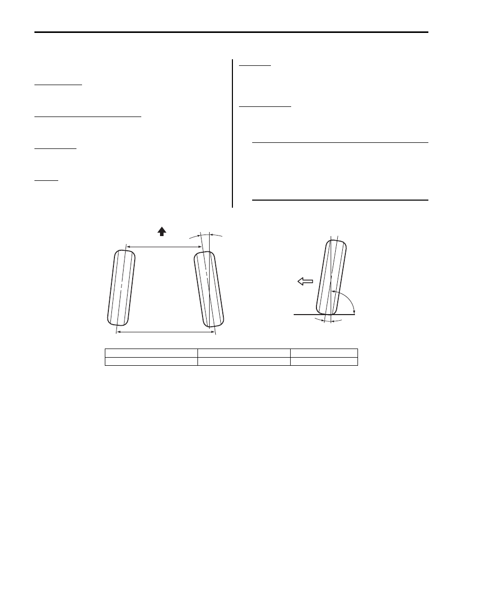
Wheel Alignment Specifications
S6JB0B2107001
Toe “b” – “a”
Front: 0.0
± 2.0 mm (0 ± 0.0787 in.)
Rear: IN 6.0
± 2.0 mm (0.2362 ± 0.0787 in.)
Toe (degree) (each wheel) “d”
Front: 0
° ± 5’
Rear: 0
° 14’ ± 5’
Camber “c”
Front: 0
° 00’ ± 1°
Rear: –1
° 15’ ± 30’
Caster
Front: 2
° 30’
Side Slip
Front: IN 1.5 to OUT 1.5 mm/m (IN 0.0591 to OUT
0.0591 in./3.3 ft)
Rear: IN 7.5 mm/m (IN 0.2953 in./3.3 ft)
Steering angle
Inside: 37.0
° ± 3°
Outside: 32.0
° ± 3°
NOTE
• Toe value in the specifications table was
measured by using a toe-in gauge.
• As for front camber, front caster and rear
caster, regulation is impossible.
• Side slip is reference information.
[A]
[B]
2
1
90˚
“c ”
“a”
“b”
F
“d ”
I6JB0B210001-02
[A]: Toe-in (Top view)
1. Center line of wheel
F: Forward
[B]: Camber (Front view)
2. Body center
Front Suspension: 2B-1
Suspension
Front Suspension
General Description
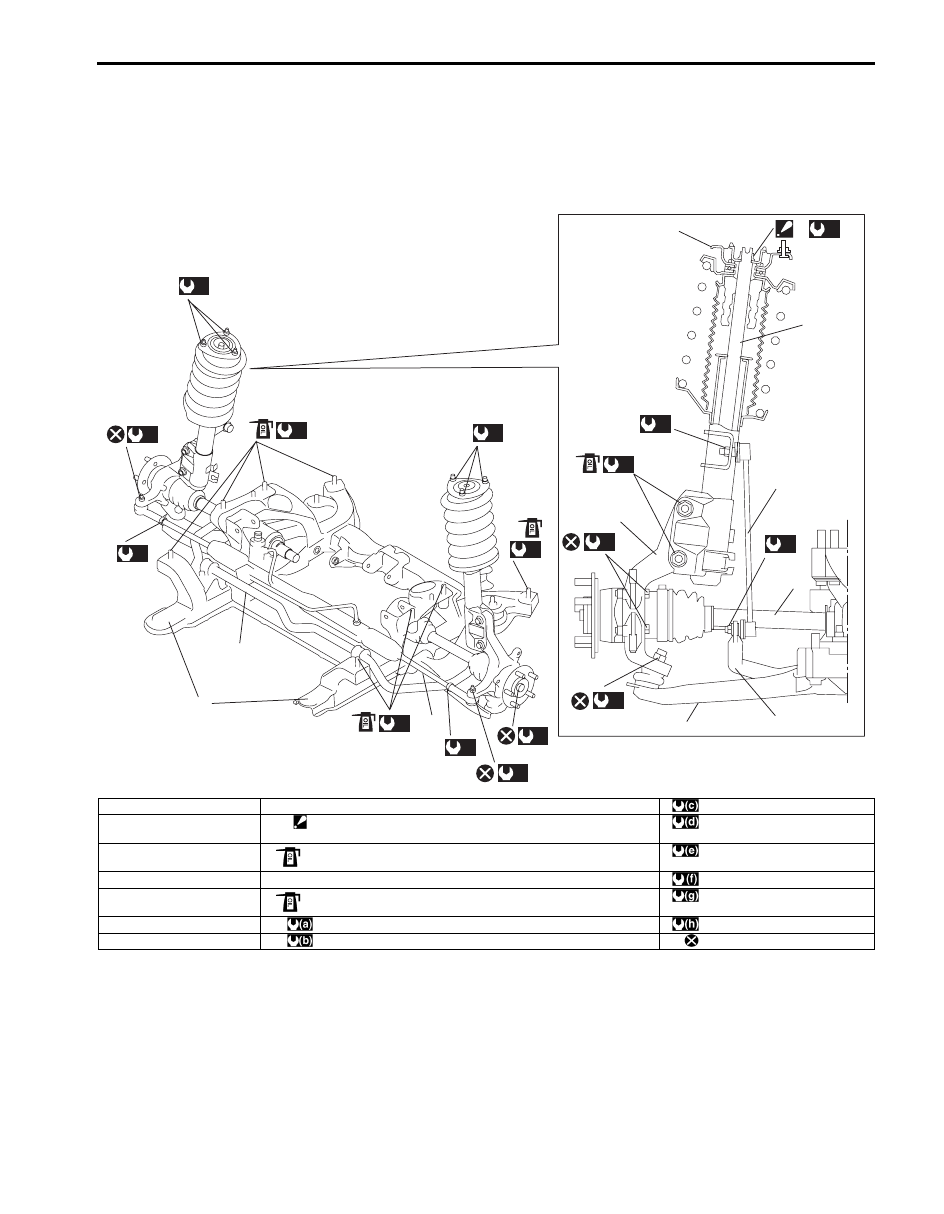
Front Suspension Construction
S6JB0B2201001
2
7
4
2
5
8
1
6
3
(b)
(c)
(d)
(e)
(f)
(g)
(h)
(h)
(b)
(b)
(f)
(g)
9
(a)
10
11
(a)
10
(a)
10
(a)
12
I6JB0B220001-02
1. Front strut assembly
8. Stabilizer bar joint
: 55 N
⋅m (5.5 kgf-m, 40.0 lb-ft)
2. Stabilizer bar
9. Strut nut
: Do not reuse caulking nut if used.
: 70 N
⋅m (7.0 kgf-m, 51.0 lb-ft)
3. Steering knuckle
10. Suspension frame bolt
: If bolt is reused, apply engine oil to thread, bearing and trunk surface.
: 220 N
⋅m (22.0 kgf-m, 159.5 lb-ft)
4. Suspension control arm
11. Suspension frame
: 65 N
⋅m (6.5 kgf-m, 47.0 lb-ft)
5. Front drive shaft
12. Strut bracket nut
: If nut is reused, apply engine oil to thread and bearing.
: 43 N
⋅m (4.3 kgf-m, 31.0 lb-ft)
6. Vehicle body
: 135 N
⋅m (13.5 kgf-m, 98.0 lb-ft)
: 60 N
⋅m (6.0 kgf-m, 43.5 lb-ft)
7. Tie-rod
: 50 N
⋅m (5.0 kgf-m, 36.5 lb-ft)
: Do not reuse.
Нет комментариевНе стесняйтесь поделиться с нами вашим ценным мнением.
Текст