Suzuki Grand Vitara JB627. Manual — part 253
5C-3 Clutch:
Diagnostic Information and Procedures
Clutch (Hydraulic Type) Symptom Diagnosis
S6JB0B5304001
Condition
Possible cause
Correction / Reference Item
Slipping
Improper clutch pedal free travel
Bleed air or replace master cylinder.
Worn or oily clutch disc facing
Replace disc.
Warped disc, pressure plate or flywheel
surface
Replace disc, clutch cover or flywheel.
Weakened diaphragm spring
Replace clutch cover.
Master cylinder piston or seal cup not
returning
Repair master cylinder.
Dragging clutch
Improper clutch pedal free travel
Bleed air or replace master cylinder.
Weakened diaphragm spring, or worn
spring tip
Replace clutch cover.
Rusted input shaft splines
Lubricate.
Damaged or worn splines of
transmission input shaft
Replace input shaft.
Excessively wobbly clutch disc
Replace disc.
Clutch facings broken or dirty with oil
Replace disc.
Fluid leakage
Repair or replace.
Clutch vibration
Glazed (glass-like) clutch facings
Repair or replace disc.
Clutch facings dirty with oil
Replace disc.
Release bearing slides unsmoothly
Replace clutch operating cylinder assembly.
Wobbly clutch disc, or poor facing
contact
Replace disc.
Weakened torsion springs in clutch disc Replace disc.
Clutch disc rivets loose
Replace disc.
Distorted pressure plate or flywheel
surface
Replace clutch cover or flywheel.
Weakened or loosened engine mounting
bolt or nut
Retighten or replace mounting.
Noisy clutch
Worn or broken release bearing
Replace clutch operating cylinder assembly.
Input shaft front bearing worn down
Replace input shaft bearing.
Excessive rattle of clutch disc hub
Replace disc.
Cracked clutch disc
Replace disc.
Pressure plate and diaphragm spring
rattling
Replace clutch cover.
Grabbing clutch
Clutch disc facings soaked with oil
Replace disc.
Clutch disc facings excessively worn
Replace disc.
Rivet heads showing out of facing
Replace disc.
Weakened torsion springs
Replace disc.
Clutch: 5C-4
Repair Instructions
Clutch Pedal Height Inspection
S6JB0B5306011
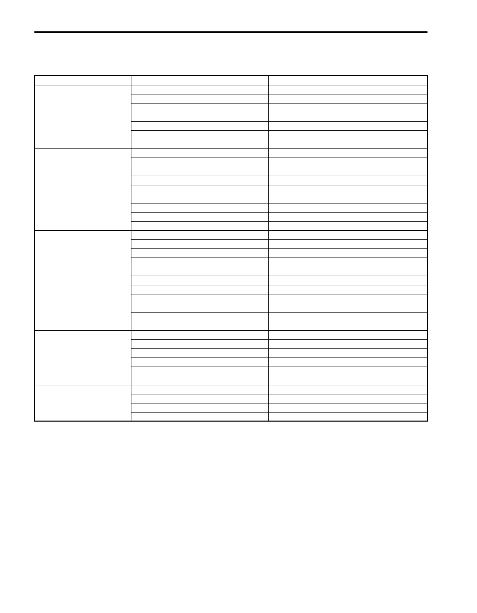
Measure clutch pedal height “a” from brake pedal (2). If
pedal height is excessive low or high, check installation
position of clutch position switch, clutch fluid leakage,
bending of clutch pedal arm and bending of push rod of
clutch master cylinder (3). If any abnormality is found,
adjust or replace it with a new one.
Clutch pedal height
“a”: Approx. 20 mm (0.79 in.)
Clutch Pedal Free Travel Check
S6JB0B5306012
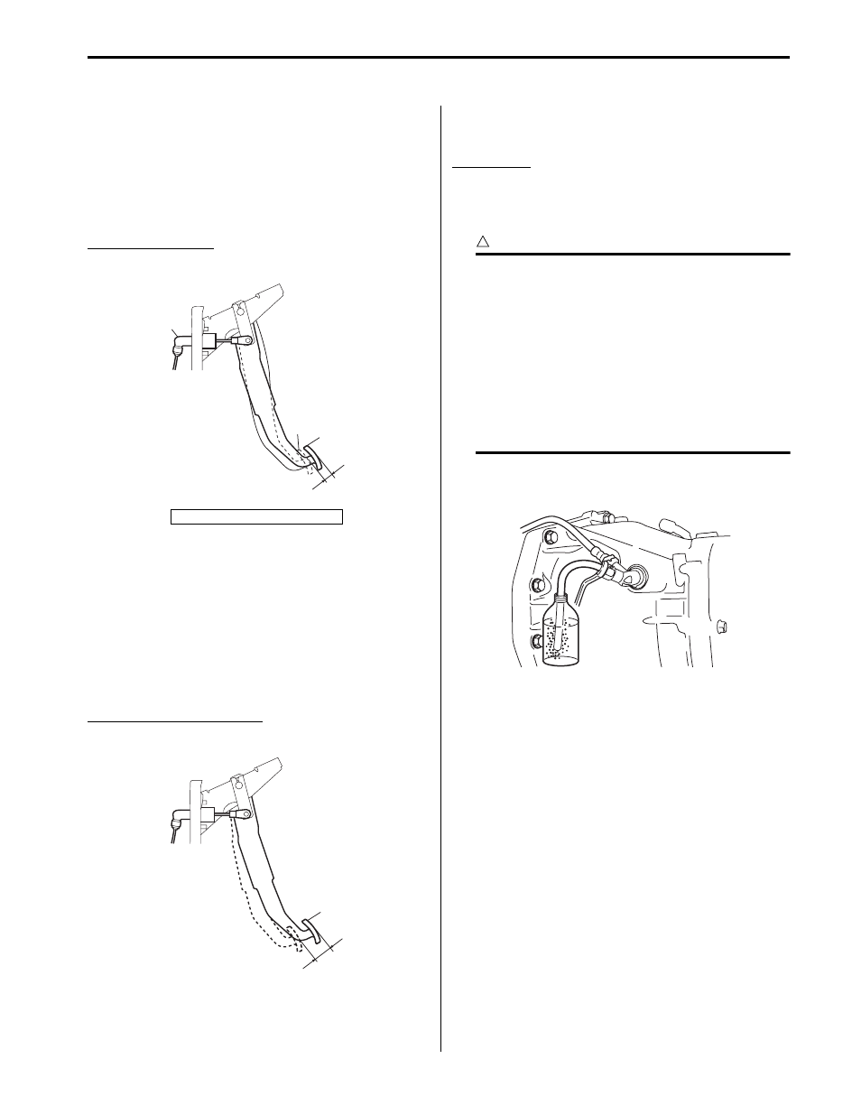
Depress clutch pedal (1), stop the moment clutch
resistance is felt and measure distance (clutch pedal
free travel). Free travel should be within the following
specification. If free travel is out of specification, check
installation position of clutch pedal position switch, clutch
fluid leakage, bending of clutch pedal arm and bending
of push rod of clutch master cylinder. If any abnormality
is found, adjust or replace it with a new one.
Clutch pedal free travel “a”
: 0 – 10 mm (0 – 0.4 in.)
Clutch Fluid Inspection
S6JB0B5306013
Refer to “Brake Fluid Level Check in Section 4A”.
Clutch Fluid
: Refer to brake reservoir cap
Air Bleeding of Clutch System
S6JB0B5306014
CAUTION
!
• Brake fluid is extremely damaging to paint.
If fluid should accidentally touch painted
surface, immediately wipe fluid from paint
and clean painted surface.
• When operating the pedal stroke for air
bleeding of clutch system, after releasing
the clutch pedal, be sure to wait 1 second
or more before depressing it again.
Otherwise, the oil seal of operating
cylinder will be damaged, resulting in oil
leakage.
Bleed air from clutch system. Refer to “Air Bleeding of
Brake System in Section 4A” for air bleeding procedure.
1. Clutch pedal
3
2
1
“a”
I5JB0A530003-01
1
“a”
I5JB0A530004-01
I5JB0A530015-03
5C-5 Clutch:
Clutch Pedal Position (CPP) Switch Removal
and Installation
S6JB0B5306001
Removal
1) Disconnect connector of CPP switch (1) with ignition
switch OFF.
2) Remove CPP switch (1) from pedal bracket.
Installation
1) Instal CPP switch to pedal bracket.
2) Adjust switch position referring to “Clutch Pedal
Position (CPP) Switch Inspection and Adjustment”.
3) Connect connector to CPP switch securely.
Clutch Pedal Position (CPP) Switch Inspection
and Adjustment
S6JB0B5306002
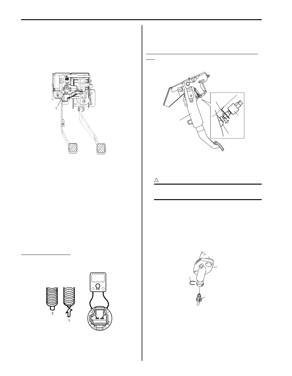
Inspection
Check for resistance between terminals under each
condition below. If check result is not satisfactory,
replace.
CPP switch resistance
When switch shaft is pushed (1): Continuity
When switch shaft is free (2): No continuity
Adjustment
With clutch pedal (1) released, adjust switch (2) position
so that clearance between end of thread and clutch
pedal arm is within specification.
Clearance between end of thread and clutch pedal
arm
“a”: 0.5 – 1.5 mm (0.02 – 0.06 in.)
Clutch Fluid Pipe and Hose Removal and
Installation
S6JB0B5306003
CAUTION
!
Do not allow fluid to get on painted surface. It
may cause painted surface damage.
Removal
1) Remove dust and dirt from each joint of hose and
pipe to be disconnected and clean around reservoir
cap of brake master cylinder.
2) Take out fluid with syringe or such.
3) Remove clamp (1) of clutch master cylinder (2) and
disconnect fluid pipe (3).
I5JB0A530005-02
I5JB0A530006-01
1
1
2
3
“a”
I5JB0A530007-02
1
2
3
I5JB0A530008-01

Clutch: 5C-6
4) Pull clamp (1) of fluid pipe joint (2) and disconnect
fluid hose (3).
Installation
Reverse removal sequence noting the following points.
• Tighten hose bracket nut (1) to specified torque.
Tightening torque
Clutch fluid hose bracket nut (a): 10 N·m (1.0 kgf-
m, 7.5 lb-ft)
• Install each clamp securely.
• After installation, check clutch pedal free travel and
bleed air from system.
• Check fluid leakage.
• Add fluid close to MAX level of reservoir.
Clutch Fluid Pipe and Hose Inspection
S6JB0B5306004
Check pipe (1) and hose (2) for dent, kink, crack, dirt and
dust. Replace if check result is not satisfactory.
Clutch Master Cylinder Removal and
Installation
S6JB0B5306005
CAUTION
!
• Do not allow fluid to get on painted
surfaces. It may cause painted surface
damage.
• Do not disassemble clutch master
cylinder.
Removal
1) Clean around reservoir cap of brake master cylinder
and take out fluid with syringe or such.
2) Detach main fuse box.
3) Disconnect fluid pipe (2) and reservoir hose (4) from
master cylinder assembly (1).
4) Remove clip (6) and push rod clevis pin (5).
5) Remove master cylinder attaching nuts (3).
6) Remove master cylinder assembly (1) and gasket.
1
3
2
I5JB0A530010-02
1, (a)
I6JB01530001-02
2
1
I6JB01530002-02
1
2
3
4
3
6
5
I5JB0A530013-01
Нет комментариевНе стесняйтесь поделиться с нами вашим ценным мнением.
Текст