Suzuki Grand Vitara JB627. Manual — part 252
5B-31 Manual Transmission/Transaxle:
NOTE
The specified tightening torque is also described in the following.
“Manual Transmission Assembly Components”
“Gear Shift Control Lever Rear Case Assembly Components”
“Gear Shift Lever Front Case Assembly Components”
“Gear Shift Shaft and Fork Components”
“Input Shaft Assembly, Output Shaft Assembly and Countershaft Assembly Components”
Reference:
For the tightening torque of fastener not specified in this section, refer to “Fastener Information in Section 0A”.
Special Tools and Equipment
Recommended Service Material
S6JB0B5208001
NOTE
Required service material is also described in the following.
“Manual Transmission Assembly Components”
“Gear Shift Control Lever Rear Case Assembly Components”
“Gear Shift Lever Front Case Assembly Components”
“Gear Shift Shaft and Fork Components”
“Input Shaft Assembly, Output Shaft Assembly and Countershaft Assembly Components”
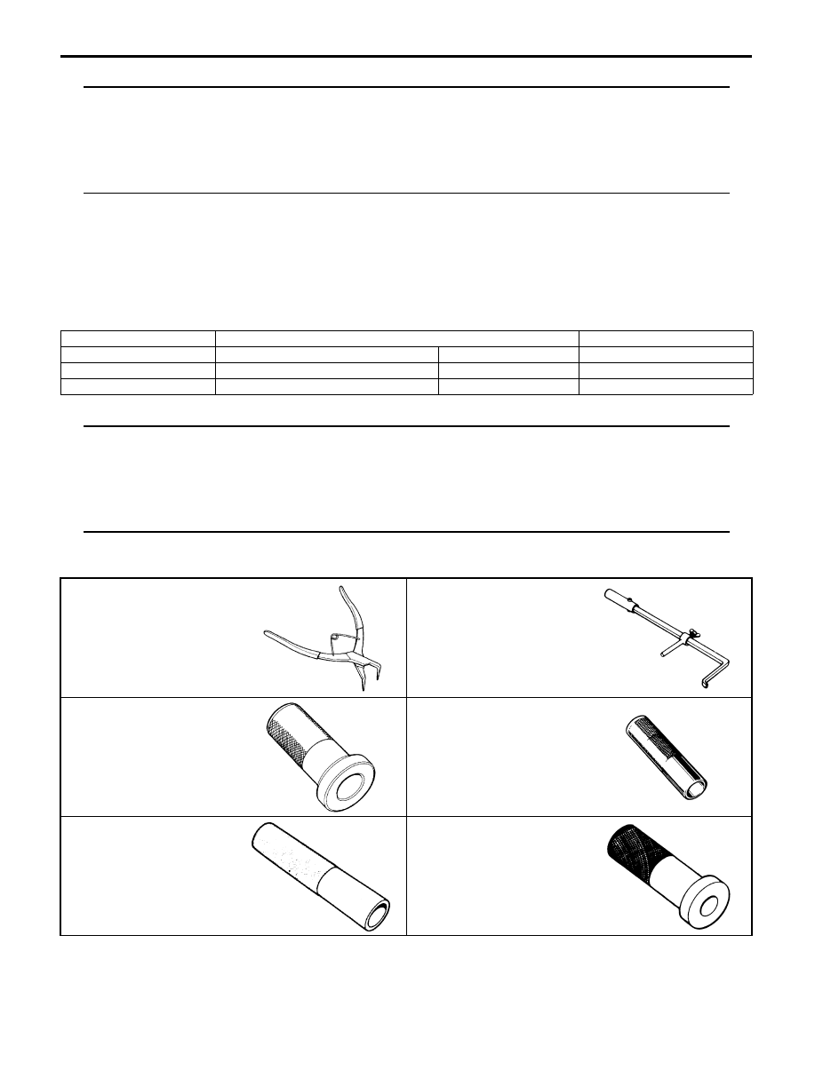
Special Tool
S6JB0B5208002
Material
SUZUKI recommended product or Specification
Note
Grease
SUZUKI Super Grease A
P/No.: 99000–25010
Sealant
SUZUKI Bond No.1217G
P/No.: 99000–31260
Thread lock cement
Thread Lock Cement Super 1322
P/No.: 99000–32110
09900–06106
09913–50121
Snap ring pliers (closing
type)
Oil seal remover
09913–75810
09913–80113
Bearing installer
Bearing installer
09913–84510
09913–85210
Bearing installer
Bearing installer

Manual Transmission/Transaxle: 5B-32
09923–46020
09925–78210
Joint pipe
Spring pin remover (6 mm)
09930–30104
09940–51710
Sliding shaft
Bearing installer
09941–64511
Bearing and oil seal remover
(30 mm Min.)
)
5C-1 Clutch:
Transmission / Transaxle
Clutch
General Description
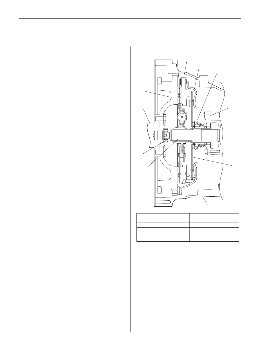
Clutch (Hydraulic Type) Construction
S6JB0B5301001
The clutch is a diaphragm-spring clutch of a dry single
disc type. The diaphragm spring is of a tapering-finger
type, which is a solid ring in the outer diameter part, with
a series of tapered fingers pointing inward.
The disc, carrying torsional coil springs, is positioned on
the transmission input shaft with an involute spline fit.
The clutch cover is secured to the flywheel, and carries
the diaphragm spring in such a way that the peripheral
edge part of the spring pushes on the pressure plate
against the flywheel (with the disc in between), when the
clutch release bearing (incorporated in clutch operating
cylinder) is held back. This is the engaged condition of
the clutch.
Depressing the clutch pedal causes the release bearing
(incorporated in clutch operating cylinder) to advance
and pushes on the tips of the tapered fingers of the
diaphragm spring. When this happens, the diaphragm
spring pulls the pressure plate away from the flywheel,
thereby interrupting the flow of drive from flywheel
through clutch disc to transmission input shaft.
Clutch fluid is supplied from brake fluid reservoir.
Clutch fluid level can be checked by brake fluid level of
brake fluid reservoir.
1. Crankshaft
7. Release bearing
2. Flywheel
8. Input shaft bearing
3. Clutch disc
9. Input shaft
4. Pressure plate
10. Operating cylinder
5. Clutch cover
11. Clutch housing
6. Diaphragm spring
1
2
3
4
5
6
7
10
8
9
11
I5JB0A530001-01
Clutch: 5C-2
Component Location
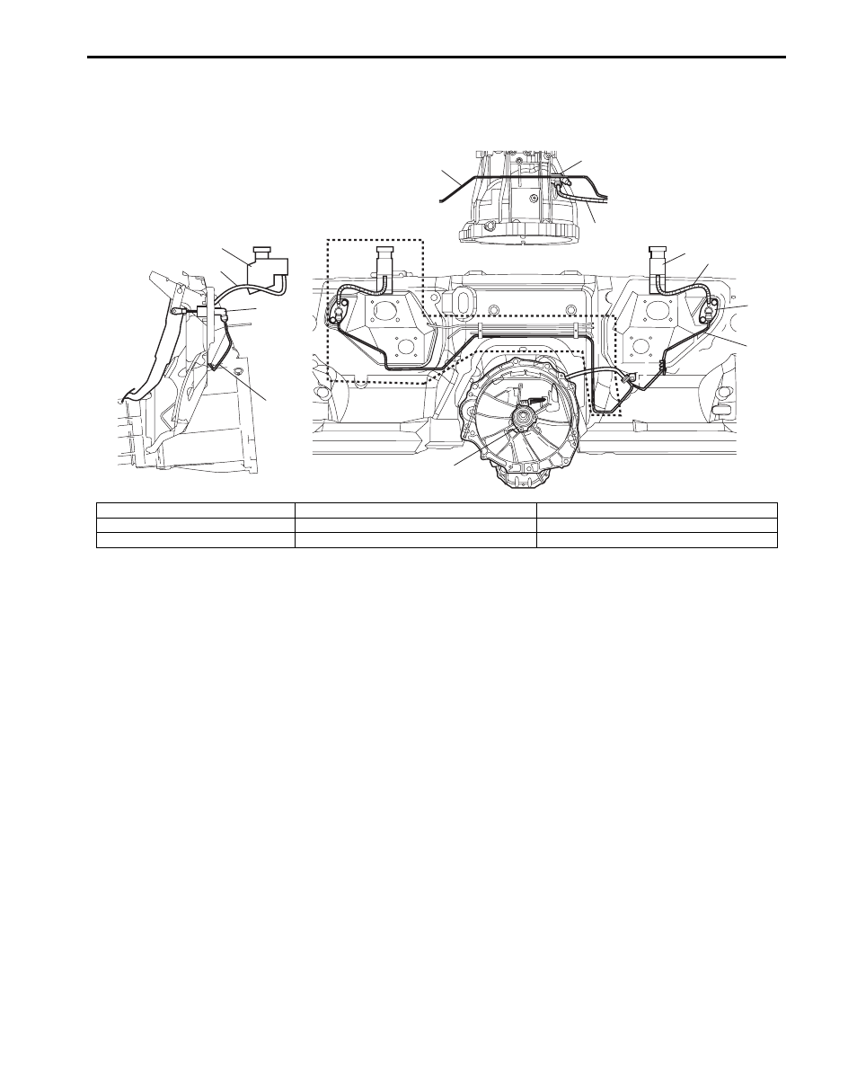
Clutch Fluid Pipe and Hose Location
S6JB0B5303001
1
1
2
2
2
3
4
5
5
6
6
7
[A]
I5JB0A530002-03
[A]: Right-hand steering vehicle
3. Clutch fluid hose
6. Brake master cylinder reservoir
1. Clutch master cylinder
4. Clutch operating cylinder assembly
7. Clutch fluid pipe joint
2. Clutch fluid pipe
5. Clutch reservoir hose
Нет комментариевНе стесняйтесь поделиться с нами вашим ценным мнением.
Текст