Suzuki Grand Vitara JB627. Manual — part 322
8B-114 Air Bag System:
WARNING
!
• For handling and storage of seat belt
pretensioner, select place where ambient
temperature is below 65
°C (150 °F),
without high humidity and away from
electric noise.
• Never carry seat belt pretensioner by
webbing.
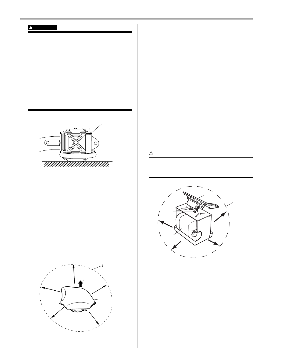
• When placing seat belt pretensioner on
workbench or other surface, be sure to lay
it with its exhaust hole (1) side facing up. It
is also prohibited to put something on seat
belt pretensioner.
Otherwise, personal injury may result.
6) Set air bag (inflator) module or seat belt pretensioner
as follows.
• For driver air bag (inflator) module
a. Clear space (3) on ground about 185 cm (6 ft)
in diameter where driver air bag (inflator)
module (1) is set for deployment. Paved,
outdoor location where there is no activity is
preferred. If outdoor location is not available,
use space on shop floor where there is no
activity and sufficient ventilation is provided.
Ensure no loose or flammable object exists
within deployment area.
b. Place driver air bag (inflator) module (1) with
its vinyl trim cover facing up (2) on ground in
step a.
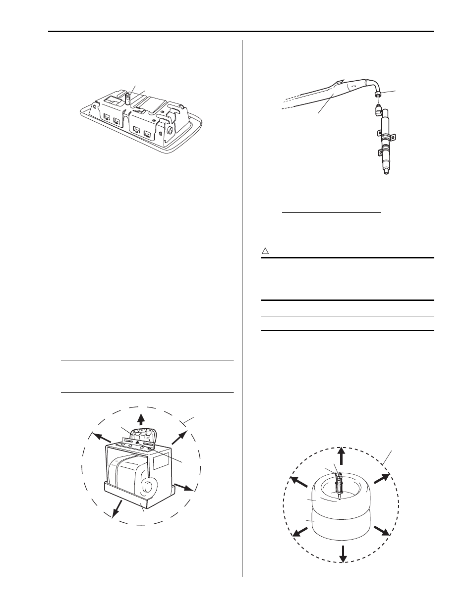
• For passenger air bag (inflator) module
a. Clear space (3) on ground about 185 cm (6 ft)
in diameter where passenger air bag (inflator)
module (1) is set for deployment. Paved,
outdoor location where there is no activity is
preferred. If outdoor location is not available,
use space on shop floor where there is no
activity and sufficient ventilation is provided.
Ensure no loose or flammable object exists
within deployment area.
b. Place deployment fixture (A) on ground in step
a.
Special tool
(A): 09932–75041
c. Fill plastic reservoir in deployment fixture (A)
with water or sand. This is necessary to
provide sufficient stabilization of fixture during
deployment.
d. Attach passenger air bag (inflator) module (1)
in deployment fixture (A) securely using M8
bolt (2).
CAUTION
!
Be sure to use M8 size and 7T strength bolt
for fixing passenger air bag (inflator) module
(1) to deployment fixture (A).
1
I4JA01822118-01
I3JA01820036-01
3
2
1
(A)
I5JB0A820099-01
Air Bag System: 8B-115
• For side-air bag (inflator) module
a. Remove sleeve (1) and sleeve lock nut (2), if
equipped.
b. Clear space (3) on ground about 185 cm (6 ft)
in diameter where side-air bag (inflator)
module for deployment. Paved, outdoor
location where there is no activity is preferred.
If outdoor location is not available, space on
shop floor where there is no activity and
provide sufficient ventilation. Ensure no loose
or flammable objects are within deployment
area.
c. Place deployment fixture (A) on ground.
Special tool
(A): 09932–75041
d. Fill plastic reservoir in deployment fixture (A)
with water or sand. This is necessary to
provide sufficient stabilization of fixture during
deployment.
e. Attach side-air bag (inflator) module (1) in
deployment fixture using mounting
attachment, sleeve lock nut and washer (2).
NOTE
Make sure that deploying direction faces as
shown in figure against mounting
attachment.
• For side curtain-air bag (inflator) module
a. Loosen nut (1) and remove bag (2) of side
curtain-air bag (inflator) module.
b. Tie side curtain-air bag inflator (1) to tire (3)
with wire harness (2) as shown.
Wire harness specifications
Stripped wire harness section 1.25 mm
2
(0.0019 in.
2
) or more (Stripped wire harness
diameter 1.25 mm (0.05 in.) or more)
CAUTION
!
Make sure that wire harness is tight. It is very
dangerous if looseness in wire harness
results in side curtain-air bag inflator flying
off due to shock from inflator deploying.
NOTE
Wind wire harness (2) around at least 3 times.
c. Clear space (5) on ground about 185 cm (6 ft)
in diameter where side curtain-air bag
(inflator) module (1) is set for deployment.
Paved, outdoor location where there is no
activity is preferred. If outdoor location is not
available, use space on shop floor where
there is no activity and sufficient ventilation is
provided. Ensure no loose or flammable
object exists within activation area.
d. Pile tire with side curtain-air bag (inflator)
module on tire (4).
2
1
I4RS0A820088-01
1
(A)
2
3
I4RS0A820089-01
1
2
I5JB0A820100-01
1
2
3
4
5
I5JB0A820101-01
8B-116 Air Bag System:
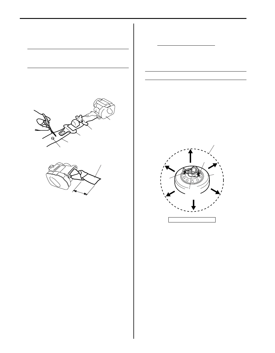
• For seat belt pretensioner
a. Cut webbing (1) at tongue plate stopper (3) of
seat belt pretensioner (2) side as shown.
NOTE
Hold seat belt pretensioner (2) vertically in
the same condition as it is installed.
Otherwise, webbing can’t be pulled out.
b. Remove tongue plate (4) and shoulder anchor
(5) from webbing.
c. Tie webbing (1) tightly at 10 cm (3.9 in.) from
cutting edge as shown.
d. Tie seat belt pretensioner (2) with wire
harness (3) to wheel-installed tire (4) as
shown.
Wire harness specifications
Stripped wire harness section 1.25 mm
2
(0.0019 in.
2
) or more (Stripped wire harness
diameter 1.25 mm (0.05 in.) or more)
NOTE
Wind wire harness (3) around at least 3 times.
e. Clear space (5) on ground about 185 cm (6 ft)
in diameter where seat belt pretensioner (2) is
to be activated. Paved, outdoor location where
there is no activity is preferred. If outdoor
location is not available, use space on shop
floor where there is no activity and sufficient
ventilation is provided. Ensure no loose or
flammable object exists within activation area.
f.
Place wheel-installed tire (4) with seat belt
pretensioner (2) on ground in step e.
7) Stretch deployment harness (A) from air bag
(inflator) module or seat belt pretensioner to its full
length 10 m (33 ft).
Special tool
(A): 09932–75031
8) Place 12 volts vehicle battery (1) near the shorted
end of deployment harness (A).
9) Check that area around air bag (inflator) module or
seat belt pretensioner is clear of all people and loose
or flammable objects.
3
1
4
5
2
I3JA01820037-01
10 cm (3.9 in.)
1
I4RS0A820104-01
1. Webbing
4
3
3
2
5
I4RS0A820105-01
Air Bag System: 8B-117
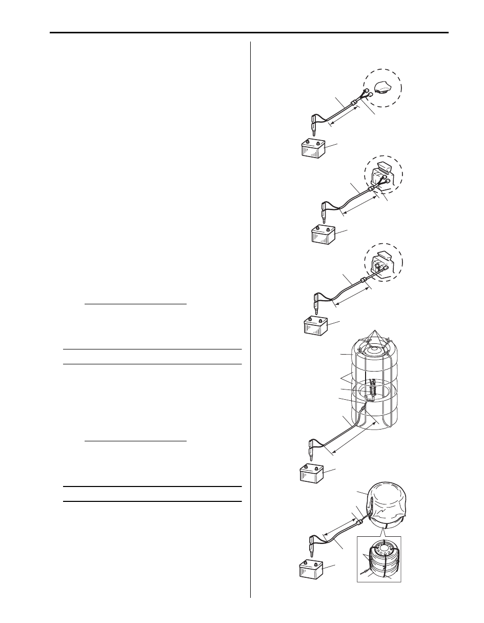
10) Connect adapter cable (B) as follows.
Special tool
(B): 09932–76510
• For driver air bag (inflator) module [A]
Check that driver air bag (inflator) module is
placed with its vinyl trim cover facing up, and
connect adapter cable (B) to driver air bag
(inflator) module.
• For passenger air bag (inflator) module [B]
Check that passenger air bag (inflator) module is
firmly and properly secured on deployment fixture
(special tool), and connect adapter cable (B) to
passenger air bag (inflator) module.
• For side-air bag (inflator) module [C]
Verify that side-air bag (inflator) module is firmly
and properly on deployment fixture (special tool),
and connect adapter cable (B) to side-air bag
(inflator) module.
• For side curtain-air bag (inflator) module [D]
a. Connect adapter cable (B) to side curtain-air
bag (inflator) module.
b. Pile 2 tires (2) and wheel-installed tire (3) on
top of tire with side curtain-air bag (inflator)
(4), and tie them with wire harness (5) as
shown.
Wire harness specifications
Stripped wire harness section 1.25 mm
2
(0.0019 in.
2
) or more (Stripped wire harness
diameter 1.25 mm (0.05 in.) or more)
NOTE
Wind wire harness (5) around at least 2 times.
• For seat belt pretensioner [E]
a. Connect adapter cable (B) to seat belt
pretensioner.
b. Pile 2 wheel-installed tires (3) on top of tire
with seat belt pretensioner (6), and tie them
with wire harness (5) as shown.
Wire harness specifications
Stripped wire harness section 1.25 mm
2
(0.0019 in.
2
) or more (Stripped wire harness
diameter 1.25 mm (0.05 in.) or more)
NOTE
Wind wire harness (5) around at least 2 times.
c. Drape blanket (7) over those tires.
11) Connect adapter cable (B) to deployment harness
(A) connector and lock connectors with lock lever.
[A]
10 m (33 ft)
(A)
(B)
1
10 m (33 ft)
(A)
(B)
1
5
3
2
4
(A)
[B]
[C]
[D]
[E]
7
3
6
5
(A)
(B)
1
10 m (33 ft)
10 m (33 ft)
(A)
(B)
1
1
10 m (33 ft)
I5JB0A820102-01
Нет комментариевНе стесняйтесь поделиться с нами вашим ценным мнением.
Текст