Suzuki Grand Vitara JB627. Manual — part 259
6B-12 Steering Wheel and Column:
Steering Lock Assembly (Ignition Switch)
Removal and Installation
S6JB0B6206009
Removal
1) Remove steering column assembly. Refer to
“Steering Column Assembly Removal and
Installation”.
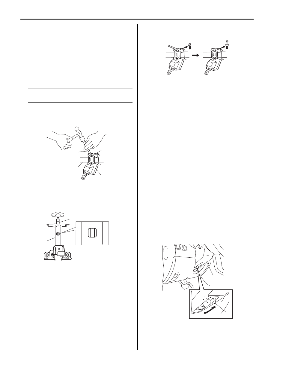
2) Using center punch (with sharp point) (1) as shown
in the figure, loosen and remove steering lock
mounting bolts (2).
NOTE
Use care not to damage aluminum part of
steering lock body (3) with center punch (1).
3) Turn ignition key to ACC or ON position and remove
steering lock assembly (3) from steering column
assembly (4).
Installation
1) Position oblong hole of steering shaft (2) in the
center of hole in steering column assembly (1).
2) Turn ignition key to ACC or ON position and install
steering lock assembly onto column.
3) Now turn ignition key to LOCK position and pull it
out.
4) Align hub on lock with oblong hole of steering shaft
and rotate shaft to assure that steering shaft is
locked.
5) Tighten new bolts until head of each bolt is broken
off.
6) Turn ignition key to ACC or ON position and check to
be sure that steering shaft rotates smoothly. Also
check for lock operation.
7) Install steering column. Refer to “Steering Column
Assembly Removal and Installation”.
8) (Keyless start model)
If steering lock assembly has replaced, after
completing installation, register steering lock unit ID
code to keyless start control module as following.
• Immobilizer model:
Register ignition key transponder code in ECM
referring to “Registration of the Ignition Key in
Section 10C”.
• Non immobilizer model:
Register steering lock unit ID code in keyless start
control module referring to “Keyless Start
Registration in Section 10E”.
Adjustable Steering Column Release Lever
Inspection
S6JB0B6206010
Check to make sure that the followings:
• Steering column (1) moves smoothly when adjustable
steering column release lever is at upper position (2)
(i.e., steering column is not locked).
• Steering column (1) is fixed securely when adjustable
steering column release lever is at lower position (3)
(i.e., steering column is locked).
1
2
4
3
I5JB0A620027-01
2
1
I5JB0A620028-01
I5JB0A620029-01
1
2
3
I5JB0A620030-01
Steering Wheel and Column: 6B-13
Steering Upper Shaft Assembly Removal and
Installation
S6JB0B6206011
CAUTION
!
Never turn steering wheel while steering
upper shaft assembly is removed.
Should it have been turned and contact coil
cable assembly have got out of its centered
position, it needs to be centered again. Also,
turning steering wheel more than about two
and a half turns will break contact coil cable
assembly.
Removal
1) Turn steering wheel so that vehicle’s front tires are at
straight-ahead position.
2) Turn ignition switch to LOCK position and remove
key.
3) Remove steering column assembly from vehicle
referring to “Steering Column Assembly Removal
and Installation”.
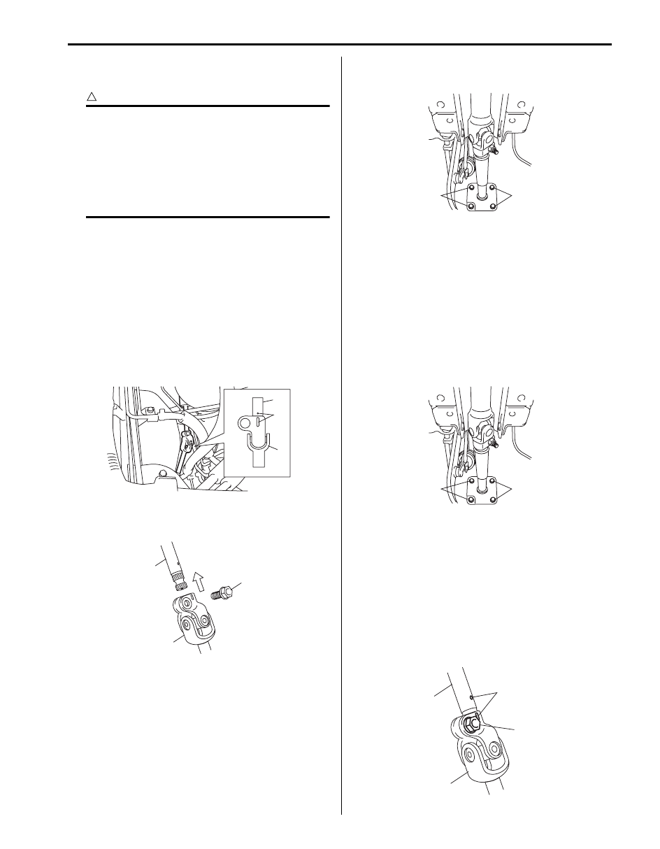
4) Make alignment marks (3) on steering upper shaft
(2) and steering lower shaft (1) for a guide during
reinstallation.
5) Remove joint bolt (1) and disconnect upper shaft (3)
from lower shaft (2).
6) Remove steering upper shaft mounting bolts (1) (4
pieces).
7) Remove steering upper shaft assembly from vehicle.
Installation
1) Be sure that front tires and steering wheel are in
straight-ahead position.
2) Install steering upper shaft assembly to dash panel.
Tighten steering upper shaft mounting bolts (1) to
specified torque.
Tightening torque
Steering upper shaft assembly mounting bolt
(a): 23 N·m (2.3 kgf-m, 17.0 lb-ft)
3) Install steering column assembly to vehicle referring
to “Steering Column Assembly Removal and
Installation”.
4) Install steering upper shaft (1) to steering lower shaft
(2) by matching it to marks (3) made before removal.
5) Install joint bolt (4). Then tighten it to specified
torque.
Tightening torque
Steering upper shaft assembly lower joint bolt
(a): 25 N·m (2.5 kgf-m, 18.0 lb-ft)
2
3
1
I5JB0A620031-01
1
3
2
I5JB0A620032-01
1
1
I5JB0A620033-01
1
1
I5JB0A620033-01
1
2
3
4, (a)
I5JB0A620034-01
6B-14 Steering Wheel and Column:
Steering Upper Shaft Assembly Inspection
S6JB0B6206012
Check steering shaft damage and operation referring to
“Checking Steering Column for Accident Damage”.
Steering Lower Shaft Assembly Removal and
Installation
S6JB0B6206013
CAUTION
!
Never turn steering wheel while steering
lower shaft assembly is removed.
Should it have been turned and contact coil
cable assembly have got out of its centered
position, it needs to be centered again. Also,
turning steering wheel more than about two
and a half turns will break contact coil cable
assembly.
Removal
1) Turn steering wheel so that vehicle’s front tires are at
straight-ahead position.
2) Turn ignition switch to LOCK position and remove
key.
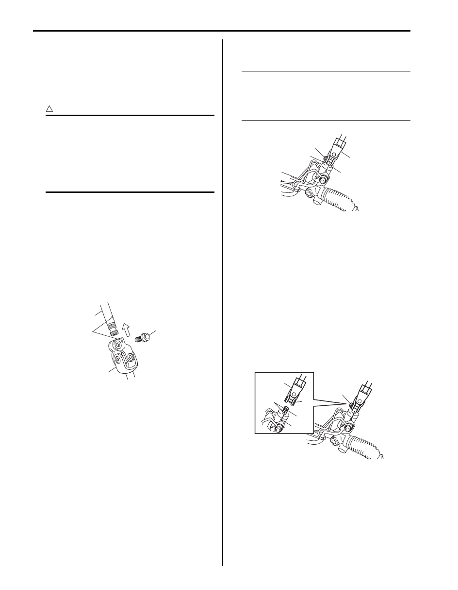
3) Make alignment marks (1) on steering upper shaft
(2) and steering lower shaft for a guide during
reinstallation.
4) Remove joint bolt (4) and disconnect upper shaft (2)
from joint (3).
5) Remove joint bolt (2) and then remove lower shaft
assembly (1).
NOTE
When yellow paint (3) cannot be confirmed
make alignment marks on steering lower
shaft assembly lower joint (1) and pinion
shaft of P/S gear case assembly (4) for a
guide during reinstallation.
Installation
1) Check for following conditions before installing lower
shaft.
• Front tires of vehicle are at straight-ahead
position.
• Match mark on gear case (6) and that on pinion
shaft (4) are aligned.
2) Install lower shaft (2) to pinion shaft (5), aligning slit
(1) in lower shaft with match mark (4) on pinion shaft
(5).
3) Install joint bolt (3) and tighten it to specified torque.
Tightening torque
Steering lower shaft assembly lower joint bolt
(a): 25 N·m (2.5 kgf-m, 18.0 lb-ft)
4
2
1
3
I5JB0A620035-02
1
4
2
3
I5JB0A620036-01
2
4
1
3
5
6
I5JB0A620037-01
Steering Wheel and Column: 6B-15
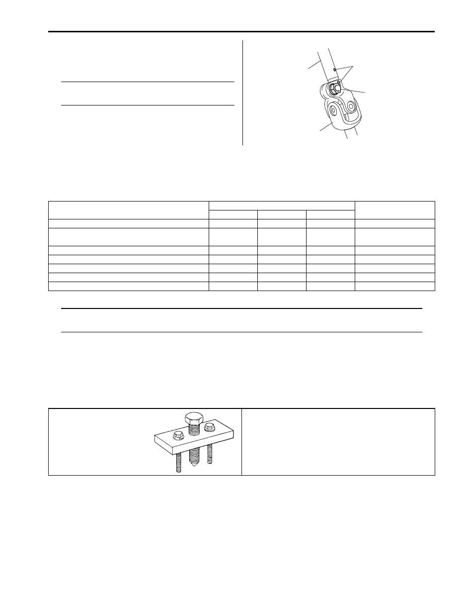
4) Install upper shaft (1) to lower shaft (3) it matching to
marks (4) made before removal.
Install joint bolt (2). Then tighten it specified torque.
NOTE
Be sue that front wheels and steering wheel
are in straight-ahead position.
Tightening torque
Steering lower shaft assembly upper joint bolt
(a): 25 N·m (2.5 kgf-m, 18.0 lb-ft)
Specifications
Tightening Torque Specifications
S6JB0B6207001
NOTE
The specified tightening torque is also described in the following.
“Steering Wheel and Column Construction”
Reference:
For the tightening torque of fastener not specified in this section, refer to “Fastener Information in Section 0A”.
Special Tools and Equipment
Special Tool
S6JB0B6208001
1
3
4
2, (a)
I5JB0A620038-01
Fastening part
Tightening torque
Note
N
⋅m
kgf-m
lb-ft
Steering shaft nut
33
3.3
24.0
Steering column assembly mounting bolt and
nut
25
2.5 18.0
Steering upper shaft assembly upper joint nut
23
2.3
17.0
Steering upper shaft assembly mounting bolt
23
2.3
17.0
Steering upper shaft assembly lower joint bolt
25
2.5
18.0
Steering lower shaft assembly lower joint bolt
25
2.5
18.0
Steering lower shaft assembly upper joint bolt
25
2.5
18.0
09944–36011
Steering wheel remover
)
Нет комментариевНе стесняйтесь поделиться с нами вашим ценным мнением.
Текст