Suzuki Grand Vitara JB627. Manual — part 257
6B-4 Steering Wheel and Column:
• Check steering shaft for smooth rotation.
If found defective, replace as column assembly.
• Check steering shaft and column for bend, cracks or
deformation.
If found defective, replace as column assembly.
• Check steering upper shaft lower seal for breakage or
deformation.
If found defective, replace.
• Check steering shaft joints and shaft for any damages
such as crack, breakage, malfunction or excessive
play.
If anything is found faulty, replace steering upper shaft
assembly, steering lower shaft assembly or steering
column assembly.
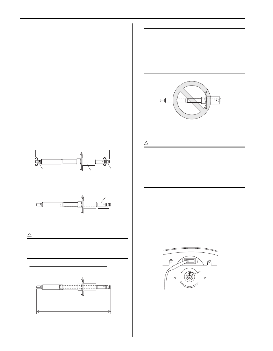
• Check steering upper shaft assembly for following
conditions.
– Steering upper shaft assembly (1) is not bent or
damaged.
– Lower seal (2) is not damaged.
– Upper joint (3) turns with light hand force and lower
joint (4) turns at the same time.
– Shaft (1) expands and contracts easily with light
force.
– When shaft is made to contract with light force until
it stops, its length “a” is longer than specified value.
CAUTION
!
Do not apply excessive force to shaft when
making it contract. Its internal plug may be
damaged.
Steering upper shaft assembly length
“a”: 363.0 mm (14.29 in.)
NOTE
If shaft has come off in sleeve due to an
accident or some other reason as shown in
figure, its internal plug has come off or been
damaged. The same applies when length of
steering upper shaft assembly is short.
When anything faulty is noted in above
check, replace steering upper shaft assembly
with a new one.
Steering Wheel Removal and Installation
S6JB0B6206002
CAUTION
!
Removal of the steering wheel allows the
contact coil cable assembly to turn freely but
do not turn the contact coil cable assembly
more than allowable number of turns (about
two and a half turns from the center position
clockwise or counterclockwise respectively),
or coil will break.
Removal
1) Remove driver air bag (inflator) module from
steering wheel referring to “Driver Air Bag (Inflator)
Module Removal and Installation in Section 8B”.
2) Disconnect horn connector and audio control switch
connector, if equipped.
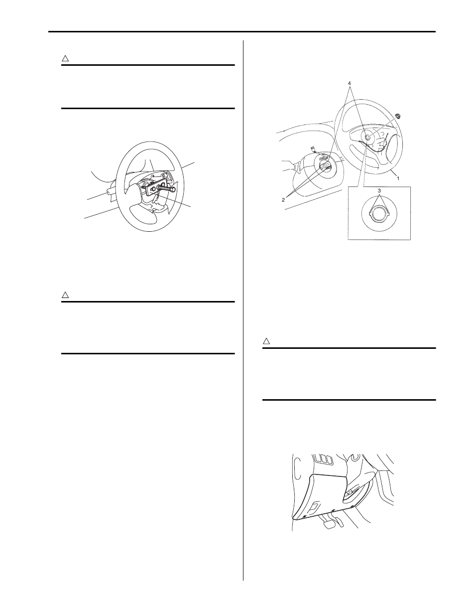
3) Remove steering shaft nut.
4) Make alignment marks (1) on steering wheel and
shaft for a guide during reinstallation.
4
2
1
3
I5JB0A620004-01
1
I5JB0A620005-01
“a”
I5JB0A620006-02
I5JB0A620007-03
1
I5JB0A620008-01
Steering Wheel and Column: 6B-5
5) Remove steering wheel (1) with special tool.
CAUTION
!
Do not hammer the end of the shaft.
Hammering it will loosen the plastic shear
pins which maintain the column length and
impair the collapsible design of the column.
Special tool
(A): 09944–36011
Installation
1) Check that vehicle’s front tires are at straight-ahead
position and contact coil cable assembly is centered.
Refer to “Centering Contact Coil Cable Assembly”.
CAUTION
!
These two conditions are prerequisite for
installation of steering wheel. If steering
wheel has been installed without these
conditions, contact coil cable assembly will
break when steering wheel is turned.
2) Install steering wheel (1) to steering shaft with 2 lugs
(2) on contact coil cable assembly fitted in two
grooves (3) in the back of steering wheel and also
aligning marks (4) on steering wheel and steering
shaft.
3) Tighten steering shaft nut to specified torque.
Tightening torque
Steering shaft nut: 33 N·m (3.3 kgf-m, 24.0 lb-ft)
4) Connect horn connector and audio control switch
connector, if necessary.
5) Install driver air bag (inflator) module to steering
wheel. Refer to “Driver Air Bag (Inflator) Module
Removal and Installation in Section 8B”.
Contact Coil Cable Assembly Removal and
Installation
S6JB0B6206003
CAUTION
!
Do not turn contact coil cable assembly more
than allowable number of turns (about two
and a half turns from the center position
clockwise or counterclockwise respectively),
or coil will break.
Removal
1) Remove steering wheel from steering column. Refer
to “Steering Wheel Removal and Installation”.
2) Remove steering column hole cover (1).
(A)
1
I5JB0A620009-01
I5JB0A620010-01
1
I5JB0A620011-01
6B-6 Steering Wheel and Column:
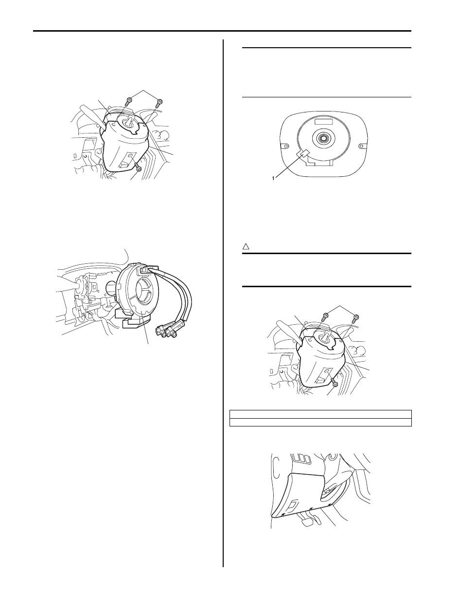
3) Remove steering column cover screws (1) (3
pieces).
4) Separate upper cover (2) and lower cover (3), then
remove them.
5) Disconnect all connectors for contact coil cable
assembly.
6) Remove contact coil cable assembly (1) with
steering angle sensor (ESP
® model) from steering
column.
7) (ESP
® model)
Separate steering angle sensor from contact coil
cable assembly referring to “Steering Angle Sensor
Removal and Installation (ESP
Installation
1) Check to make sure that vehicle’s front tires are set
at straight-ahead position and then ignition switch is
at “LOCK” position.
2) (ESP
® model)
Install steering angle sensor to contact coil cable
assembly refer to “Steering Angle Sensor Removal
and Installation (ESP
3) Install contact coil cable assembly to steering
column noting the following.
• Fit lower fitting part first and then fit upper fitting
part.
NOTE
New contact coil cable assembly is supplied
with contact coil cable assembly set and held
at its center position with a lock pin (1).
Remove this lock pin after installing contact
coil cable assembly to steering column.
4) Connect all connectors that have been removed in
“Removal”.
5) Install steering column upper cover (2) and lower
cover (3), and then tighten steering column cover
screws (1).
CAUTION
!
When installing lower cover (3) and upper
cover (2), be careful so that each lead wire is
not caught between covers.
6) Install steering column hole cover (1).
7) Install steering wheel to steering column. Refer to
“Steering Wheel Removal and Installation”.
1
3
1
2
I5JB0A620012-01
1
I6JB01620002-01
*: Standard screw
**: Tapping screw
I5JB0A620014-01
1*
3
1**
2
I5JB0A620015-01
1
I5JB0A620011-01
Steering Wheel and Column: 6B-7
Contact Coil Cable Assembly Inspection
S6JB0B6206004
CAUTION
!
Do not turn contact coil cable assembly more
than allowable number of turns (about two
and a half turns from the center position
clockwise or counterclockwise respectively),
or coil will break.
Check contact coil cable assembly (1) wire harness for
any signs of scorching, melting or other damage.
If it is damaged, replace.
Centering Contact Coil Cable Assembly
S6JB0B6206005
CAUTION
!
Removal of the steering wheel allows the
contact coil cable assembly to turn freely but
do not turn the contact coil cable assembly
more than allowable number of turns (about
two and a half turns from the center position
clockwise or counterclockwise respectively),
or coil will break.
1) Check that vehicle’s wheels (front tires) are set at
straight-ahead position.
2) Check that ignition switch is at LOCK position.
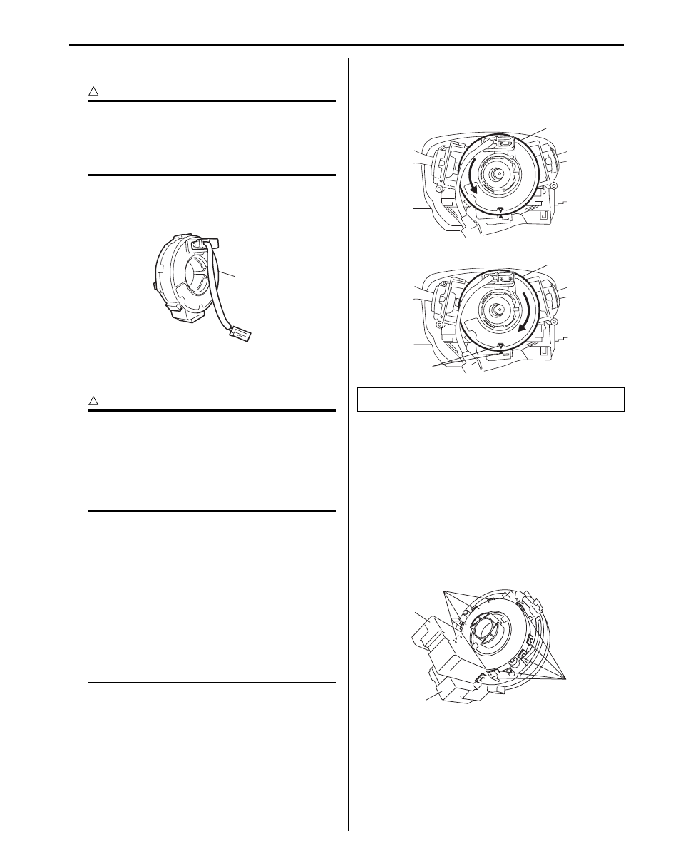
3) Turn contact coil cable assembly (2)
counterclockwise slowly with a light force till contact
coil cable assembly will not turn any further.
NOTE
Contact coil cable assembly can turn about 5
turns at maximum, that is, if it is at the center
position, can turn about two and a half turns
both clockwise and counterclockwise.
4) From the position where contact coil cable assembly
(2) became unable to turn any further (it stopped),
turn it back clockwise about two and a half rotations
and align center mark with alignment mark (1).
Steering Angle Sensor Removal and Installation
(ESP
® Model)
S6JB0B6206014
Removal
1) Remove steering wheel and contact cable assembly.
Refer to “Steering Wheel Removal and Installation”
and “Contact Coil Cable Assembly Removal and
Installation”.
2) Remove steering angle sensor (2) from contact coil
cable assembly (3) while opening fitting parts (1) of
contact coil cable assembly.
1
I5JB0A620016-01
[A]: Turn slowly till coil stops
[B]: Turn contact coil cable assembly back about 2 and a half turns
1
2
2
[A]
[B]
I5JB0A620017-03
1
1
2
3
I6JB01620003-01
Нет комментариевНе стесняйтесь поделиться с нами вашим ценным мнением.
Текст