Suzuki Grand Vitara JB627. Manual — part 98
1D-73 Engine Mechanical:
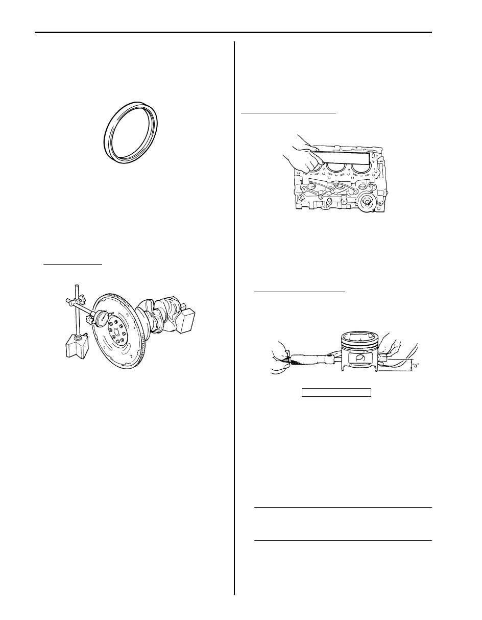
Rear Oil Seal and Flywheel Inspection
S6JB0B1406047
Rear Oil Seal
Carefully inspect oil seal for wear or damage. If lip
portion is worn or damaged, replace oil seal.
Flywheel
• If ring gear is damaged, cracked or worn, replace
flywheel.
• If the surface contacting clutch disc is damaged or
excessively worn, replace flywheel.
• Check flywheel for face runout with a dial gauge. If
runout exceeds its limit, replace flywheel.
Flywheel runout
Limit: 0.2 mm (0.0078 in.)
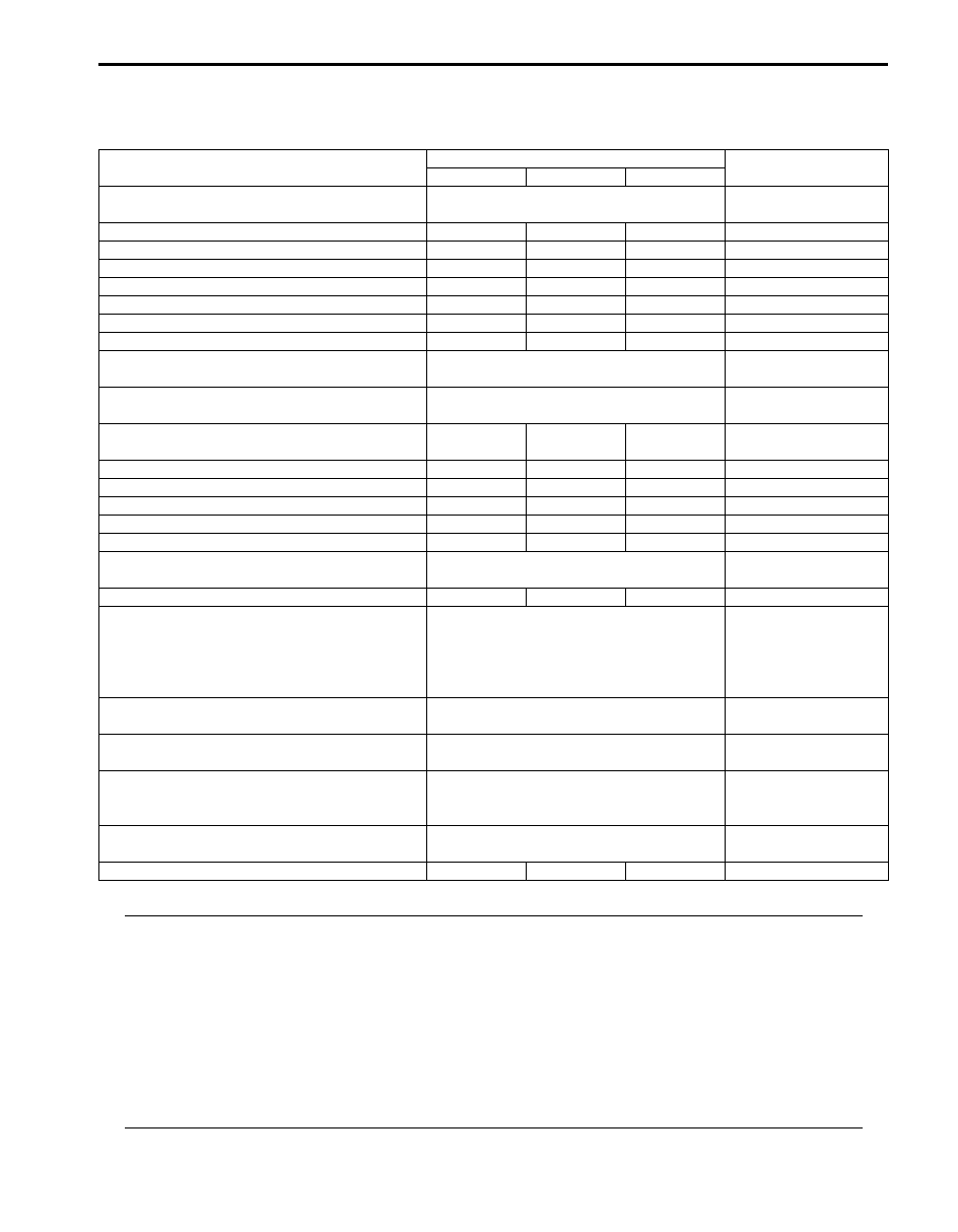
Cylinder Block Inspection
S6JB0B1406048
Distortion of Gasketed Surface
Using straightedge and thickness gauge, check
gasketed surface for distortion. If flatness exceeds its
limit, correct or replace it.
Gasketed surface flatness
Limit: 0.06 mm (0.0024 in.)
Honing or reboring cylinders
1) When any cylinder needs reboring, all other
cylinders must also be rebored at the same time.
2) Select oversized piston according to amount of
cylinder wear.
Oversize piston diameter
88.470 – 88.490 mm (3.4831 – 3.4838 in.)
3) Using micrometer, measure piston diameter.
4) Calculate cylinder bore diameter to be rebored as
follows.
D = A + B – C
D: Cylinder bore diameter to be rebored
A: Piston diameter as measured
B: Piston clearance = 0.02 – 0.04 mm (0.0008 –
0.0015 in.)
C: Allowance for honing = 0.02 mm (0.0008 in.)
5) Rebore and hone cylinder to calculated dimension.
NOTE
Before reboring, install lower crankcase in
place and tighten to specification to avoid
distortion of bearing bores.
6) Measure piston clearance after honing.
IYSQ01143168-01
IYSQ01143169-01
“a”: 26.5 mm (1.04 in.)
IYSQ01143170-01
I6JB01140107-01
Engine Mechanical: 1D-74
Specifications
Tightening Torque Specifications
S6JB0B1407001
NOTE
The specified tightening torque is also described in the following.
“Air Intake System Components”
“Engine Mounting Components”
“Timing Chain Cover Components”
“LH (No.1) Bank 2nd Timing Chain and Chain Tensioner Components”
“1st Timing Chain and Chain Tensioner Components”
“RH (No.2) Bank 2nd Timing Chain and Chain Tensioner Components”
“Camshafts, Tappets and Shims Components”
“Valves and Cylinder Heads Components”
“Pistons, Piston Rings, Connecting Rods and Cylinders Components”
“Main Bearings, Crankshaft and Cylinder Block Components”
Reference:
For the tightening torque of fastener not specified in this section, refer to “Fastener Information in Section 0A”.
Fastening part
Tightening torque
Note
N
⋅m
kgf-m
lb-ft
Camshaft housing bolts
11 N
⋅m (1.1 kgf-m, 7.5 lb-ft) by the specified
procedure
Camshaft housing bolt
11
1.1
8.0
Cylinder head cover nut
10.5
1.1
7.5
Engine block heater mounting bolt
11
1.1
8.0
Timing chain cover bolt
11
1.1
8.0
Crankshaft pulley bolt
150
15
108.5
Timing chain guide No.4 bolt
11
1.1
8.0
Camshaft timing sprocket bolt
80
8.0
58.0
Timing chain tensioner adjuster No.3 bolt
Tighten 11 N
⋅m (1.1 kgf-m, 7.5 lb-ft) by the
specified procedure
Timing chain tensioner adjuster No.3 nut
Tighten 45 N
⋅m (4.5 kgf-m, 32.5 lb-ft) by the
specified procedure
RH (No.2) bank 1st timing chain intake camshaft
sprocket bolt
80
8.0 58.0
Timing chain tensioner nut
25
2.5
18.0
Idler sprocket No.1 bolt
55
5.5
40.0
Timing chain tensioner adjuster No.1 bolt
11
1.1
8.0
Timing chain guide No.1 and No.2 bolt
9
0.9
6.5
Timing chain tensioner adjuster No.2 bolt
11
1.1
8.0
Camshaft housing bolt
11 N
⋅m (1.1 kgf-m, 8.0 lb-ft) by the specified
procedure
Timing chain guide No.3 bolt
11
1.1
8.0
Cylinder head bolt
Tighten 53 N
⋅m (5.3 kgf-m, 38.5 lb-ft), 84
N
⋅m (8.4 kgf-m, 61.0 lb-ft), 0 N⋅m (0 kgf-m,
0 lb-ft), 53 N
⋅m (5.3 kgf-m, 38.5 lb-ft) and
105 N
⋅m (10.5 kgf-m, 76.0 lb-ft) by the
specified procedure
Cylinder head bolt (hex hole bolt)
Tighten 11 N
⋅m (1.1 kgf-m, 7.5 lb-ft) by the
specified procedure
Connecting rod bolt
Tighten 15 N
⋅m (1.5 kgf-m,11.0 lb-ft), 45°
and 45
° by the specified procedure.
Lower crankcase bolt (10 mm (0.39 in.) thread
diameter)
Tighten 30 N
⋅m (3.0 kgf-m,22.0 lb-ft), 0 N⋅m
(0 kgf-m, 0 lb-ft), 42 N
⋅m (4.2 kgf-m, 30.5 lb-
ft) and 40
° by the specified procedure
Lower crankcase bolt (8 mm (0.31 in.) thread
diameter)
27 N
⋅m (2.7 kgf-m,19.5 lb-ft) by the
specified procedure
Flywheel (or drive plate) bolt
70
7.0
51.0
1D-75 Engine Mechanical:
Special Tools and Equipment
Recommended Service Material
S6JB0B1408001
NOTE
Required service material is also described in the following.
“Timing Chain Cover Components”
“LH (No.1) Bank 2nd Timing Chain and Chain Tensioner Components”
“1st Timing Chain and Chain Tensioner Components”
“RH (No.2) Bank 2nd Timing Chain and Chain Tensioner Components”
“Camshafts, Tappets and Shims Components”
“Valves and Cylinder Heads Components”
“Pistons, Piston Rings, Connecting Rods and Cylinders Components”
“Main Bearings, Crankshaft and Cylinder Block Components”
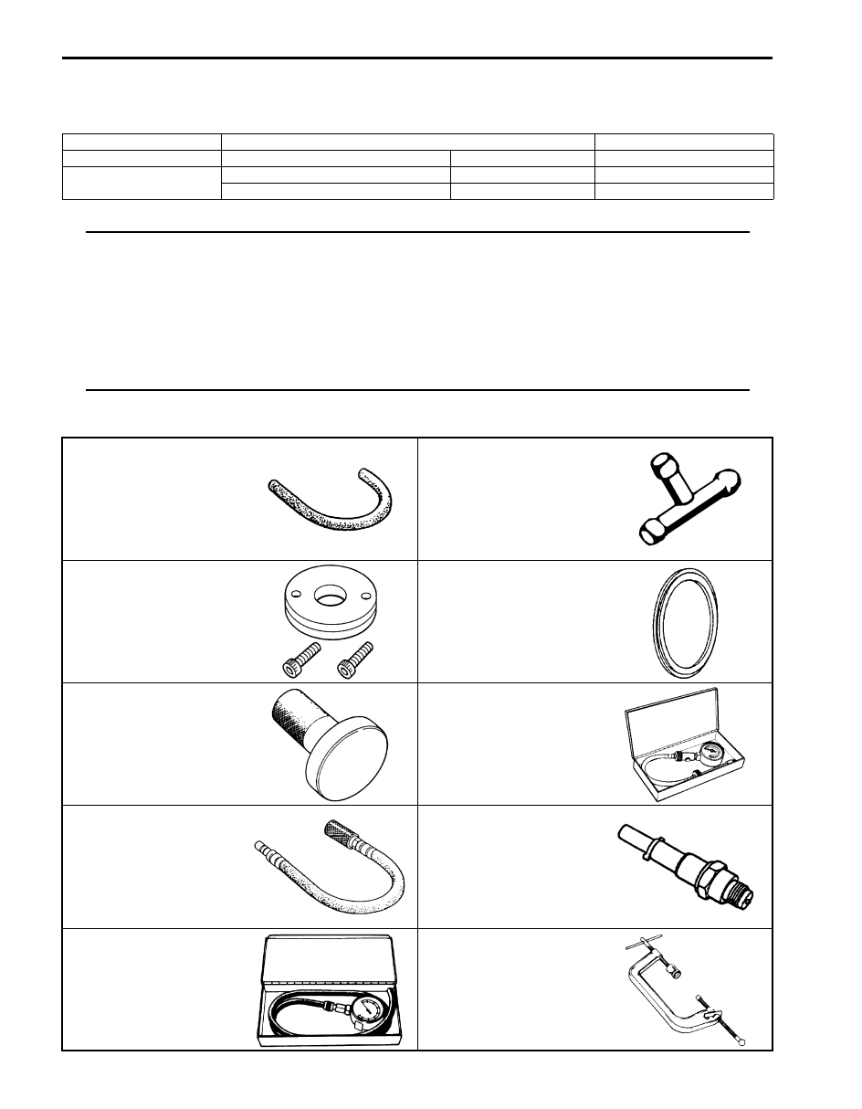
Special Tool
S6JB0B1408002
Material
SUZUKI recommended product or Specification
Note
Sealant
SUZUKI Bond No.1217G
P/No.: 99000–31260
Water tight sealant
SUZUKI Bond No.1207B
P/No.: 99000–31140
SUZUKI Bond No.1207F
P/No.: 99000–31250
09355–35754–600
09367–04002
Hose
3-way joint
09911–97710
09911–97811
Oil seal guide
Oil seal installer
09913–75510
09915–64512
Bearing installer
Compression gauge
09915–64530
09915–67010
Compression gauge hose
Compression gauge
attachment (C)
09915–67311
09916–14510
Vacuum gauge
Valve lifter
Engine Mechanical: 1D-76
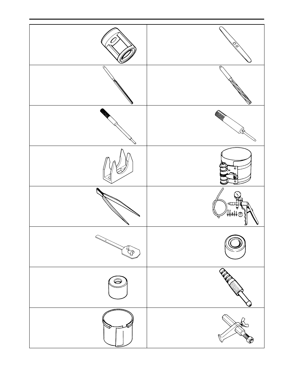
09916–14910
09916–34542
Valve spring compressor
attachment
Reamer handle
09916–37810
09916–38210
Valve guide reamer (6 mm)
Valve guide reamer (11 mm)
09916–44910
09916–58210
Valve guide installer &
remover
Valve guide installer handle
09916–66510
09916–77310
Tappet holder
Piston ring compressor (50-
125 mm)
09916–84511
09917–47011
Forceps
Vacuum pump gauge
09917–68221
09917–87810
Camshaft pulley holder
Valve guide installer
attachment (protrusion: 13.5
mm)
09917–98221
09918–08210
Valve guide stem
attachment
Vacuum gauge hose joint
09919–28610
09924–17811
Protector sleeve
Flywheel holder
Нет комментариевНе стесняйтесь поделиться с нами вашим ценным мнением.
Текст