Suzuki Grand Vitara JB627. Manual — part 270
7A-12 Heater and Ventilation:
HVAC Control Module Removal and Installation
S6JB0B7106011
Removal
1) Disconnect negative (–) cable at battery.
2) Remove center garnish with audio unit (if equipped)
and HVAC control module referring to “Audio Unit
Removal and Installation in Section 9C”.
3) Remove HVAC control module mounting screws and
then, remove HVAC control module (2) from center
garnish (1).
Installation
Reverse removal procedure.
HVAC Control Module and Its Circuits
Inspection (for Vehicle without A/C)
S6JB0B7106012
HVAC control module and its circuits inspection is the
same as vehicle equipped with A/C system.
Refer to “HVAC Control Module and Its Circuits
Inspection in Section 7B”.
Air Flow Control Actuator Removal and
Installation
S6JB0B7106013
Removal
1) Disconnect negative (–) cable at battery.
2) Remove steering column hole cover from instrument
panel.
3) Disconnect air flow control actuator connector (2).
4) Remove screws and then, remove air flow control
actuator (1) from HVAC unit.
Installation
Reverse removal procedure.
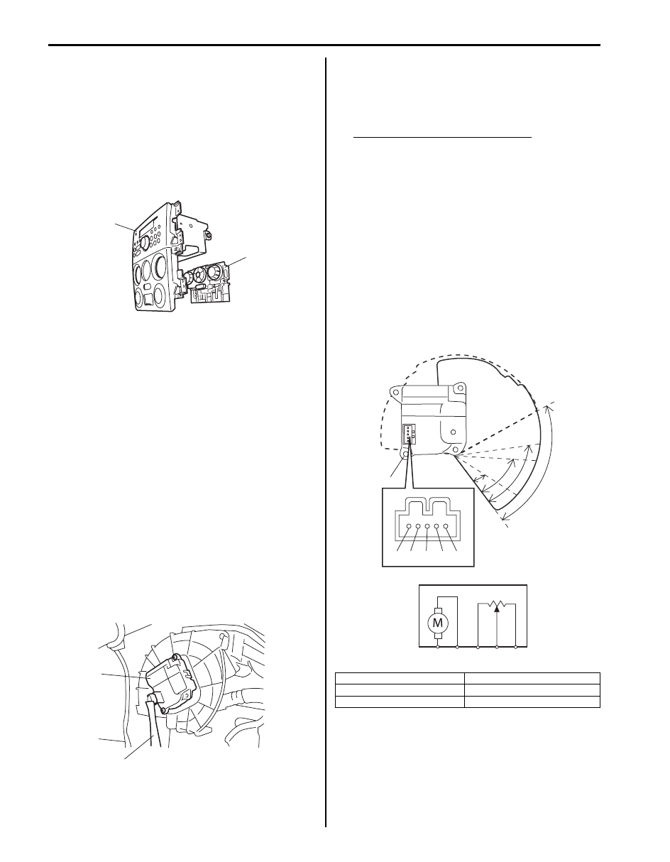
Air Flow Control Actuator Inspection
S6JB0B7106014
1) Remove air flow control actuator (1) referring to “Air
Flow Control Actuator Removal and Installation”.
2) Check resistance between “d” and “e” terminals.
Air flow control actuator resistance
DEF position: Approx. 700
Ω
FOOT / BENT position: Approx. 1.7 k
Ω
FOOT position: Approx. 2.4 k
Ω
BI-LEVEL position: Approx. 3.9 k
Ω
VENT position: Approx. 5.1 k
Ω
3) Connect battery positive (+) terminal to terminal “a”
and battery negative (–) terminal to terminal “b”.
Check if position of air flow control actuator changes
VENT position to DEF position.
4) Connect battery positive (+) terminal to terminal “b”
and battery positive (–) terminal to terminal “a”.
Check if position of air flow control actuator changes
DEF position to VENT position.
If malfunction is found, replace air flow control
actuator with new one.
1
2
I5JB0A710013-01
1
2
I5JB0A710014-02
A: VENT position
D: DEF / FOOT position (Approx. 50
°)
B: BI-LEVEL position (Approx. 22
°)
E: DEF position
C: FOOT position (Approx. 40
°)
F: Approx. 82
°
“a”
“b”
“c”
“d”
“e”
E
D
C
B
F
A
1
“a” “b” “c”
“d” “e”
I5JB0A710015-03
Heater and Ventilation: 7A-13
Temperature Control Actuator Removal and
Installation
S6JB0B7106015
Removal
1) Disconnect negative (–) cable at battery.
2) Remove steering column hole cover from instrument
panel.
3) Disconnect temperature control actuator connector
(2).
4) Remove screws (3) and then, remove temperature
control actuator (1) from HVAC unit.
Installation
Reverse removal procedure.
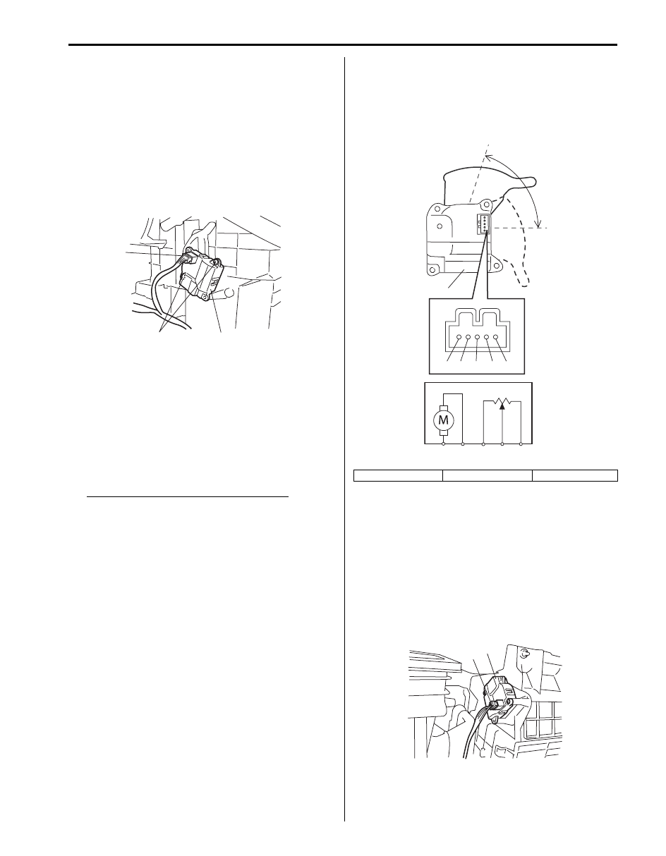
Temperature Control Actuator Inspection
S6JB0B7106016
1) Remove temperature control actuator (1). Refer to
“Temperature Control Actuator Removal and
Installation”.
2) Check resistance between “d” and “e” terminals.
Temperature control actuator resistance
Max cold position: Approx. 480
Ω
Max hot position: Approx. 3.9 k
Ω
3) Connect battery positive (+) terminal to terminal “b”
and battery negative (–) terminal to terminal “a”.
Check if position of actuator lever changes COLD
position to HOT position.
4) Connect battery positive (+) terminal to terminal “a”
and battery positive (–) terminal to terminal “b”.
Check if position of actuator lever changes HOT
position to COLD position.
If malfunction is found, replace temperature control
actuator with new one.
Air Intake Control Actuator Removal and
Installation
S6JB0B7106017
Removal
1) Disconnect negative (–) cable at battery.
2) Remove glove box.
3) Disconnect air intake control actuator connector (2).
4) Remove screws and then, remove air intake control
actuator (1) from HVAC unit.
Installation
Reverse removal procedure.
2
1
3
I5JB0A710016-01
A: Max cold position
B: Max hot position
C: Approx. 72
°
“a”
“b”
“c”
“d”
“e”
A
C
B
1
“a” “b” “c”
“d” “e”
I5JB0A710017-03
1
2
I5JB0A710018-01
7A-14 Heater and Ventilation:
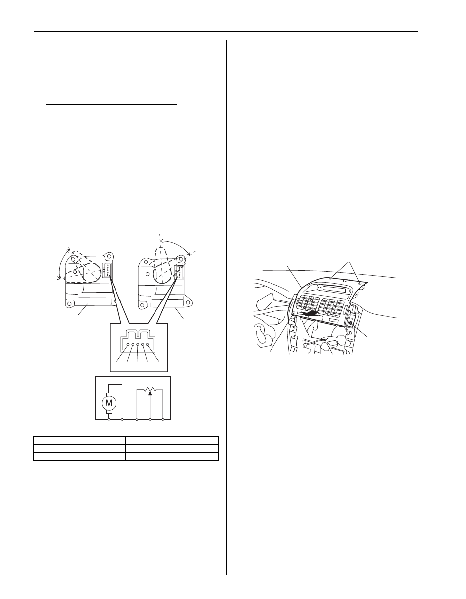
Air Intake Control Actuator Inspection
S6JB0B7106018
1) Remove air intake control actuator (1). Refer to “Air
Intake Control Actuator Removal and Installation”.
2) Check resistance between “d” and “e” terminals of
actuator.
Air intake control actuator resistance
LH steering vehicle
REC position: Approx. 4.5 k
Ω
FRE position: Approx. 1.2 k
Ω
RH steering vehicle
REC position: Approx. 1.2 k
Ω
FRE position: Approx. 4.5 k
Ω
3) Connect battery positive (+) terminal to terminal “a”
and battery negative (–) terminal to terminal “b”.
Check if position of actuator lever is REC position.
4) Connect battery positive (+) terminal to terminal “b”
and battery negative (–) terminal to terminal “a”.
Check if position of actuator lever is FRESH position.
Actuator Linkage Inspection
S6JB0B7106019
• Check if each actuator linkage operates smoothly.
• Check actuator rod for bend.
• Check each actuator linkage for breakage.
• Make sure if there is not any obstruction in operating
range of actuator linkage.
If any malfunction is found, repair or replace faulty
part(s).
Center Ventilation Louver Removal and
Installation
S6JB0B7106020
Removal
1) Disconnect negative (–) cable at battery.
2) Disable air bag system referring to “Disabling Air
3) Remove center garnish with audio unit and HVAC
control module referring to “Audio Unit Removal and
Installation in Section 9C”.
4) Remove mounting screw (1) and then pull off center
ventilation louver (2).
5) Disconnect connectors and remove center
ventilation louver.
6) Remove center ventilation louver from center
garnish.
[A]: LH steering vehicle
D: FRESH position
[B]: RH steering vehicle
E: Approx. 60
°
C: REC position
“a”
“b”
“c”
“d”
“e”
“a” “b” “c” “d”
“e”
1
C
E
D
C
E
[A]
[B]
D
1
I5JB0A710019-03
3. Clip
1
1
2
3
I5JB0A710020-01
Heater and Ventilation: 7A-15
Installation
Reverse removal procedure, noting the following item.
Insert backside of center ventilation louver to ventilator
duct surely.
• When installing center ventilation louver, align boss
(1) and claws (2) with installation hole of instrument
panel.
• Enable air bag system referring to “Enabling Air Bag
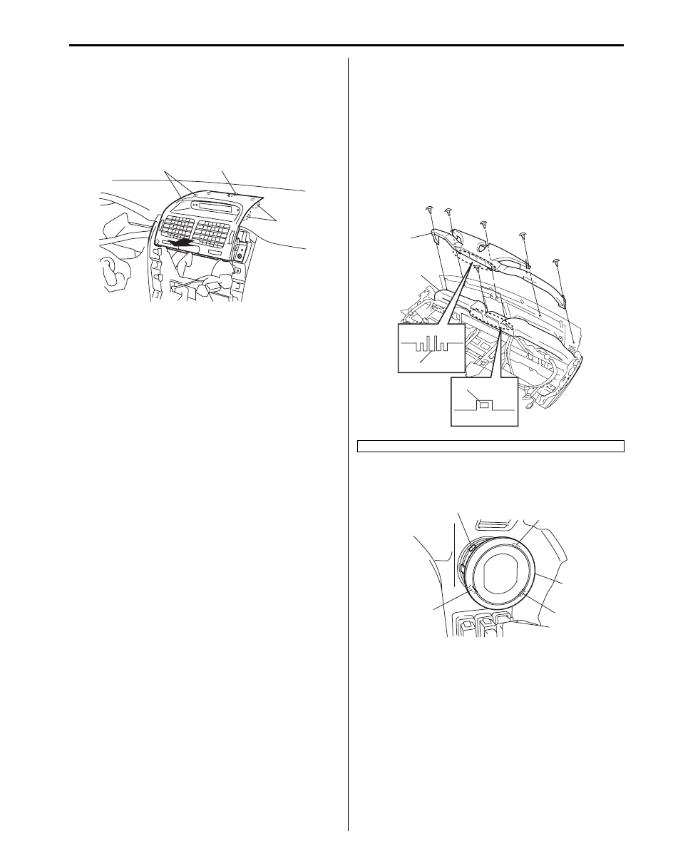
Side Ventilation Louver Removal and
Installation
S6JB0B7106021
Removal
1) Remove steering column hole cover.
2) Remove instrument panel referring to “Instrument
Panel Removal and Installation in Section 9C”.
3) Remove screws and claws (3), and then remove
defroster duct (2) from instrument panel.
4) Remove ventilator duct (1) from instrument panel.
5) Remove side ventilation louver (1) from instrument
panel while pressing claws (2).
2
2
1
I5JB0A710021-01
4. hole
2
1
3
4
I5JB0A710022-02
2
1
2
2
2
I5JB0A710023-01
Нет комментариевНе стесняйтесь поделиться с нами вашим ценным мнением.
Текст