Suzuki Grand Vitara JB627. Manual — part 41

1A-113 Engine General Information and Diagnosis:
DTC P0300 / P0301 / P0302 / P0303 / P0304 / P0305 / P0306: Misfire Detected
S6JB0B1104037
System Description
ECM measure the angle of the crankshaft based on the pulse signal from the CKP sensor and CMP sensor for each
cylinder. If it detects a large change in the angle speed of the crankshaft, it concludes occurrence of a misfire. When
the number of misfire is counted by ECM beyond the DTC detecting condition, it determine the cylinder where the
misfire occurred and output it as DTC.
DTC Detecting Condition and Trouble Area
DTC Confirmation Procedure
WARNING
!
• When performing a road test, select a place where there is no traffic or possibility of a traffic
accident and very careful during testing to avoid occurrence of an accident.
• Road test should be carried out with 2 persons, a driver and a tester, on a level road.
NOTE
Check to make sure that the following conditions are satisfied when using this “DTC Confirmation
Procedure”.
• Atmospheric pressure: higher than 75 kpa (560 mmHg) (Altitude: lower than 2790 m (9150 ft)).
• Engine coolant temperature: higher than –10
°C (14 °F).
• Make sure that the ignition timing is good referring to “Ignition Timing Inspection in Section 1H”.
1) With ignition switch OFF, connect scan tool.
2) Turn ON ignition switch and clear DTC by using scan tool if any.
3) Drive vehicle more than 37 mph (60 km/h) for more than 1 minute.
4) Stop vehicle and check DTC and pending DTC by using scan tool.
5
TP sensor check
1) Check TP sensor for performance referring to “Electric
Throttle Body Assembly On-Vehicle Inspection in
Section 1C”.
Is it in good condition?
Substitute a known
good ECM and recheck.
Replace electric throttle
body assembly.
Step
Action
Yes
No
DTC detecting condition
Trouble area
P0300: Random
• Misfire, which causes catalyst to overheat during 200 engine revolutions, is
detected at 2 or more cylinders. (MIL flashes as long as this misfire occurs
continuously.)
• Misfire, which affects exhaust emission adversely during 1000 engine revolutions,
is detected at 2 or more cylinders.
(2 driving cycle detection logic)
• Ignition system
• Fuel injector and its circuit
• Fuel pressure
• EGR system (if equipped)
• Fuel level sensor
• Abnormal air drawn in
• Engine compression
• Valve lash (clearance)
• Valve timing
• Fuel shortage
• Exhaust system
• Fuel of poor quality
P0301: No.1 cylinder, P0302: No.2 cylinder, P0303: No.3 cylinder, P0304: No.4
cylinder, P0305: No.5 cylinder, P0306: No.6 cylinder
• Misfire, which causes catalyst to overheat during 200 engine revolutions, is
detected at 1 cylinder. (MIL flashes as long as this misfire occurs continuously.)
• Misfire, which affects exhaust emission adversely during 1000 engine revolutions,
is detected at 1 cylinder.
(2 driving cycle detection logic)

Engine General Information and Diagnosis: 1A-114
DTC Troubleshooting
Step
Action
Yes
No
1
Was “Engine and Emission Control System Check”
performed?
Go to Step 2.
Go to “Engine and
Emission Control
System Check”.
2
Does fuel level meter indicate “E” level (empty)?
Add fuel and recheck.
Go to Step 3.
3
Air intake system and exhaust system inspection
1) Check air intake system and exhaust system for
leakage.
Are intake system and exhaust system in good condition?
Go to Step 4.
Repair or replace.
4
Ignition system inspection
1) Check spark plug and ignition spark of cylinder where
misfire occurs, referring to “Spark Plug Inspection in
Section 1H” and “Ignition Spark Check in Section 1H”.
Is it in good condition?
Go to Step 5.
Faulty ignition coil, wire
harness or spark plug. If
OK, substitute a known
good ECM and recheck.
5
Fuel injector and its circuit check
1) Check fuel injector circuit referring to “Fuel Injector
Is it in good condition?
Go to Step 6.
Repair or replace.
6
Fuel pressure inspection
1) Check fuel pressure referring to “Fuel Pressure Check”.
Is check result satisfactory?
Go to Step 7.
Repair or replace.
7
Fuel injector inspection
1) Check fuel injector(s) referring to “Fuel Injector
Is check result satisfactory?
Go to Step 8.
Replace.
8
EGR system inspection (if equipped)
1) Check EGR system referring to “EGR System Inspection
Is check result satisfactory?
Go to Step 9.
Repair or replace.
9
Fuel level sensor inspection
1) Check fuel level sensor referring to “Fuel Level Sensor
Is check result satisfactory?
Go to Step 10.
Repair or replace.
10 Engine mechanical systems check
1) Check engine mechanical systems.
• Engine compression: Refer to “Compression Check in
• Valve lash: Refer to “Valve Lash (Clearance)
• Valve timing: Refer to “LH (No.1) Bank 2nd Timing
Chain and Chain Tensioner Removal and Installation
in Section 1D” and “1st Timing Chain and Chain
Tensioner Removal and Installation in Section 1D”.
Are they in good condition?
Substitute a known
good ECM and recheck.
Repair or replace.
1A-115 Engine General Information and Diagnosis:
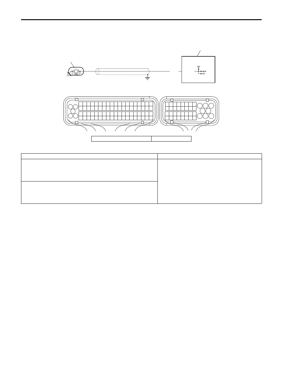
DTC P0327 / P0328: Knock Sensor Circuit Low / High
S6JB0B1104038
Wiring Diagram
DTC Detecting Condition and Trouble Area
DTC Confirmation Procedure
1) Connect scan tool to DLC with ignition switch turned OFF.
2) Turn ON ignition switch and clear DTC pending DTC and freeze frame data by using scan tool.
3) Start engine and run it for 1 minute.
4) Check DTC by using scan tool.
1
2
5V
1
3 2
4
5
6
7
8
9
1110
12
13
14
15
16
17
18
19
20
17
18
19
20
21
22
23
24
25
26
27
28
29
30
31
33
34
35
36
37
38
39
40
32
1
2
3
4
5
6
7
8
9
10
11
12
13
14
15
16
21
22
23
24
25
26
27
28
29
30
31
32
33
34
35
36
37
38
39
40
41
42
43
44
45
46
47
48
49
50
51
52
53
54
55
56
57
58
59
60
61
62
63
64
65
66
67
68
69
70
71
72
73
74
75
76
77
78
79
80
81
E23
C37
C37-25
WHT
I5JB0C110011-01
1. Knock sensor
2. ECM
DTC detecting condition
Trouble area
DTC P0327: Knock Sensor Circuit Low
Output voltage of knock sensor is less than 1 V for more than 255
ignition times continuously.
(1 driving cycle detection logic)
• Knock sensor and its circuit
• ECM
DTC P0328: Knock Sensor Circuit High
Output voltage of knock sensor is more than 4 V for more than 255
ignition times continuously.
(1 driving cycle detection logic)

Engine General Information and Diagnosis: 1A-116
DTC Troubleshooting
NOTE
Before this trouble shooting is performed, read the precautions for DTC troubleshooting referring to
“Precautions for DTC Troubleshooting”.
Step
Action
Yes
No
1
Was “Engine and Emission Control System Check”
performed?
Go to Step 2.
Go to “Engine and
Emission Control
System Check”.
2
Knock sensor circuit voltage check
1) Turn ignition switch OFF position.
2) Disconnect connector from knock sensor.
3) Check for proper terminal connection to knock sensor
and ECM connectors
4) If connections are OK, turn ignition switch to ON
position.
5) Check that circuit voltage is 5 V between knock sensor
signal circuit of knock sensor connector and vehicle
body ground.
Is it in good condition?
Replace knock sensor. Go to Step 3.
3
Wire harness check
1) Disconnect connector from ECM with ignition switch
turned OFF.
2) Check that knock sensor signal circuit is as follows.
• Wiring harness resistance of knock sensor signal
circuit is less than 3
Ω.
• Insulation resistance of knock sensor signal circuit is
infinity between knock sensor connector and vehicle
body ground.
• Circuit voltage of knock sensor signal circuit is 0 – 1 V
with ignition switch turned ON.
Are they in good condition?
Substitute a known
good ECM and recheck.
Repair or replace
defective wire harness.
Нет комментариевНе стесняйтесь поделиться с нами вашим ценным мнением.
Текст