Suzuki: Engine K6A-YH6. Manual — part 6
4
4-1
Chapter 4
Theory of Operation
General Engine Operation . . . . . . . . . . . . . . . . . . . . . . . . . . . . . . . . . . . . . . . . . . . . . . . . . 4-2
Air Intake, Fuel, and Exhaust . . . . . . . . . . . . . . . . . . . . . . . . . . . . . . . . . . . . . . . . . . . . . . . 4-4
Cooling System . . . . . . . . . . . . . . . . . . . . . . . . . . . . . . . . . . . . . . . . . . . . . . . . . . . . . . . . . . 4-5
Thermostat . . . . . . . . . . . . . . . . . . . . . . . . . . . . . . . . . . . . . . . . . . . . . . . . . . . . . . . . . . . . . . 4-6
Water Pump . . . . . . . . . . . . . . . . . . . . . . . . . . . . . . . . . . . . . . . . . . . . . . . . . . . . . . . . . . . . . 4-6
Front Cover, Timing Chain, and Tensioner . . . . . . . . . . . . . . . . . . . . . . . . . . . . . . . . . . . . 4-7
Front Cover . . . . . . . . . . . . . . . . . . . . . . . . . . . . . . . . . . . . . . . . . . . . . . . . . . . . . . . . . . . . . . 4-8
Timing Chain . . . . . . . . . . . . . . . . . . . . . . . . . . . . . . . . . . . . . . . . . . . . . . . . . . . . . . . . . . . . . 4-8
Tension Adjuster . . . . . . . . . . . . . . . . . . . . . . . . . . . . . . . . . . . . . . . . . . . . . . . . . . . . . . . . . . 4-8
Cylinder Head and Valve Train . . . . . . . . . . . . . . . . . . . . . . . . . . . . . . . . . . . . . . . . . . . . . . 4-9
Head Gasket . . . . . . . . . . . . . . . . . . . . . . . . . . . . . . . . . . . . . . . . . . . . . . . . . . . . . . . . . . . . 4-10
Camshaft . . . . . . . . . . . . . . . . . . . . . . . . . . . . . . . . . . . . . . . . . . . . . . . . . . . . . . . . . . . . . . . 4-10
Lubrication System . . . . . . . . . . . . . . . . . . . . . . . . . . . . . . . . . . . . . . . . . . . . . . . . . . . . . . 4-11
Cylinder Block and Lower Crankcase . . . . . . . . . . . . . . . . . . . . . . . . . . . . . . . . . . . . . . . 4-13
Crankshaft . . . . . . . . . . . . . . . . . . . . . . . . . . . . . . . . . . . . . . . . . . . . . . . . . . . . . . . . . . . . . . 4-13
Connecting Rod . . . . . . . . . . . . . . . . . . . . . . . . . . . . . . . . . . . . . . . . . . . . . . . . . . . . . . . . . . 4-14
Piston, Piston Rings, and Piston Pin . . . . . . . . . . . . . . . . . . . . . . . . . . . . . . . . . . . . . . . . . . 4-14
4-2
THEORY OF OPERATION
4
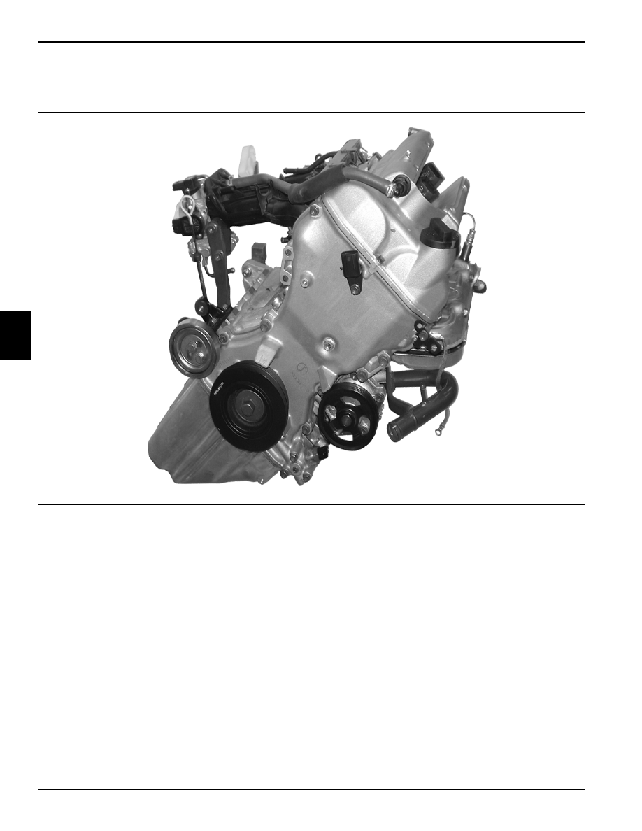
4.1 General Engine Operation
Figure 4-1
The K6A engine is an in-line, 3-cylinder, twin overhead
cam, 4-valve per cylinder, naturally aspirated, liquid
cooled, gasoline engine.
The compact K6A engine is constructed primarily of
durable, lightweight, heat-dissipating materials.
The cylinder head is a twin cam 4-valve type and made of
aluminum alloy that is light in weight and excellent in heat
dissipation. Valves are direct driven from camshafts by
way of shim-adjustable tappets placed on top of valves.
The combustion chamber is a pent-roof type with the
spark plug arranged in the center for improved
combustion. Spark plugs are fired by direct mounted
individual coils for each plug.
The camshafts are made of lightweight hollow cast iron.
Camshaft drive is done with a chain drive that is
automatically adjusted by a chain tensioner. The chain
tensioner uses lubrication system pressure and spring
pressure to automatically compensate for chain wear.
The cylinder head gasket is of 2-layer laminated stainless
steel which is excellent in durability and reliability. Use of
advanced coatings further enhance the fluid sealing
capabilities of the gasket.
The cylinder block is of a lightweight aluminum two-piece
design, consisting of upper and lower castings. The lower
casting is a ladder design that incorporates the main
journal caps for added rigidity. Semi-wet pressed-in
cylinder sleeves are contained in the upper block casting.
The crankshaft is constructed of cast iron and utilizes
four main journals and three rod journals. Counter-
balancing is achieved by weights on two of the journals.
Rod and main journal bearings are of a two-piece design
with the third main journal incorporating a thrust bearing.
Connecting rods are of a two-piece design made of
carbon steel. The rod cap is retained, using special
reamer type rod bolts and nuts.
TN0746
THEORY OF OPERATION
4-3
4
Pistons attached to connecting rods are made of an
aluminum alloy and use a full-floating piston pin. Piston
pin holes are equipped with a “Ricardo Groove” to aid in
lubrication. Pistons incorporate a slipper skirt with three
rings: two compression and one oil type.
The engine lubrication system incorporates a lightweight
aluminum oil pan with internal crankshaft baffle. Engine
oil is removed from the pan through a strainer pickup by a
crankshaft driven oil pump with integral oil pressure
regulator. Engine oil is routed through a full-flow oil filter
that houses an internal filter bypass valve and then
distributed throughout the engine.
A belt-driven water pump removes coolant from a full-flow
radiator and circulates the coolant through the entire
engine. The coolant temperature is controlled by the
cylinder-head-mounted thermostat housing containing
the thermostat.
The electronically controlled fuel injection system
efficiently supplies fuel to the engine, while maintaining
optimum performance and throttle response. Port
injectors with a common fuel rail in conjunction with a
throttle body are used for fuel distribution.

4-4
THEORY OF OPERATION
4
4.2 Air Intake, Fuel, and Exhaust
Figure 4-2
Fuel is supplied from the fuel rail (2) to each cylinder via
electronically controlled fuel injectors (1), mounted to the
intake manifold (3) runners.
Air flow into the intake manifold is metered with a throttle
body assembly (4), which is fastened and sealed to the
intake manifold. The throttle body is controlled and
monitored by the ECM to adjust fuel/air mixtures.
Exhaust gases are expelled through the exhaust side of
the cylinder head into the exhaust manifold (5), which is
fastened and sealed to the cylinder head. Exhaust gases
are monitored with the oxygen sensor (6), which provides
the ECM with data to adjust fuel/air mixtures. The entire
exhaust manifold is surrounded by a heat shield (7) to aid
in prevention of accidental burns.
1
Injector (3 used)
5
Exhaust Manifold
2
Fuel Rail
6
Oxygen Sensor
3
Intake Manifold
7
Heat Shield
4
Throttle Body Assembly
TN0690
1
2
3
4
5
6
7
Нет комментариевНе стесняйтесь поделиться с нами вашим ценным мнением.
Текст