Suzuki: Engine K6A-YH6. Manual — part 7
THEORY OF OPERATION
4-5
4
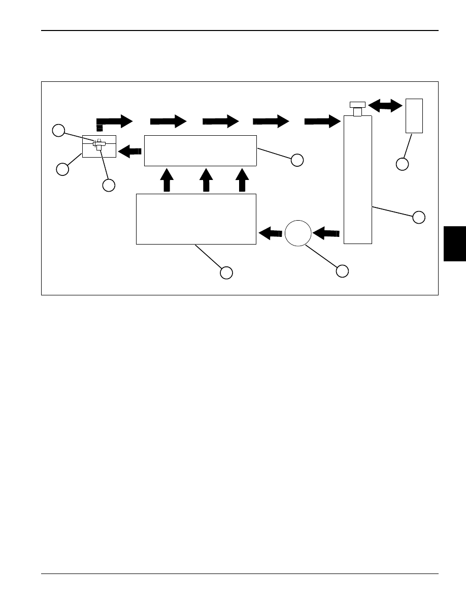
4.3 Cooling System
Figure 4-3
The cooling system includes the radiator (4), water pump
(5), thermostat (7), and engine coolant passages.
Coolant is circulated from the water pump (5) into the
engine coolant passages and circulates around the
cylinders. From the cylinders, coolant flows up through
the block deck passages and into the cylinder head (2).
In the cylinder head (2), the coolant flows through
passages around the intake and exhaust ports, valve
seats, and combustion chambers. Coolant flows toward
the rear of the cylinder head (2) and exits through the
thermostat housing (8).
During the warm-up period, the thermostat (7) is closed
and coolant flows only through the jiggle pin (1) opening
to provide a fast warm-up period. The jiggle pin (1) also
helps ensure that no air is trapped in the engine when
filling the cooling system.
Once the engine has reached operating temperature, the
thermostat (7) opens and allows coolant to flow through
the upper radiator hose to the radiator (4) top tank.
Coolant circulates through the radiator (4), dissipates
heat, and then flows out of the radiator (4) through the
lower hose and into the suction side of the water pump
(5).
If coolant temperature begins to become excessive, the
radiator pressure cap will open and allow excess coolant
to flow into the overflow bottle (3). When coolant
temperature lowers enough, the radiator cap will close.
As the coolant continues to cool, a vacuum will be
created in the radiator (4). This will open a valve in the
radiator cap that will syphon the excess coolant from the
overflow bottle (3) back into the radiator (4).
Coolant continues flowing through the engine and
radiator circuit until the coolant temperature drops below
the thermostat (7) opening temperature. The thermostat
(7) will remain open until coolant temperature falls below
the thermostat closing temperature. At that time the
thermostat (7) will close and begin a new cycle of
warming the coolant.
This repeated cycle of temperature control keeps the
engine at the optimal temperature for clean and efficient
performance.
1
Jiggle Pin
5
Water Pump
2
Cylinder Head
6
Cylinder Block
3
Overflow Bottle
7
Thermostat
4
Radiator
8
Thermostat Housing
4
5
6
7
8
1
3
2

4-6
THEORY OF OPERATION
4
Thermostat
Figure 4-4
The cooling system thermostat (1) is contained in the
thermostat housing located on the rear of the cylinder
head. The thermostat controls the flow of coolant through
the engine. The thermostat is in the closed position when
the engine is cold. When coolant temperature reaches
190° F (88° C) the thermostat begins to open, allowing
coolant to circulate. The thermostat opens fully when
coolant temperature reaches 205° F (96° C), allowing full
coolant system circulation. As engine load is varied, the
thermostat will vary its open or closed percentage to
maintain the engine in an optimum temperature range. A
jiggle pin is provided in the thermostat to aid in the
bleeding of the system when filling.
Water Pump
Figure 4-5
The engine is equipped with a belt-driven water pump (1)
driven from the crankshaft pulley. The water pump
circulates coolant throughout the entire cooling system.
The water pump is equipped with a “weep hole” for
indication of seal wear. The pump is serviceable as a unit
only.
TN0573
1
TN0747
1
THEORY OF OPERATION
4-7
4
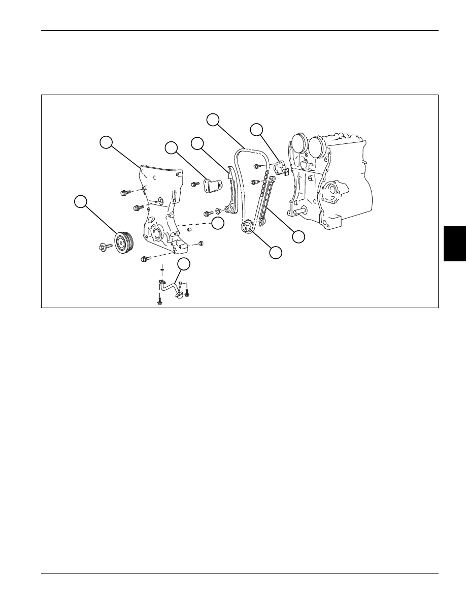
4.4 Front Cover, Timing Chain,
and Tensioner
Figure 4-6
Attached to the front of the engine is the one-piece cast
aluminum front cover. The front cover attaches the oil
pump pickup strainer and houses the oil pump and front
seal. Contained under the front cover is the timing chain,
chain guide, and chain tensioner setup.
1
Crankshaft Pulley
6
Tension Adjuster
2
Front Cover
7
Chain Guide
3
Tensioner Link
8
Crankshaft Sprocket
4
Tensioner
9
Oil Pump
5
Timing Chain
10
Pickup Strainer
TN0748
1
2
3
4
5
6
7
8
9
10
4-8
THEORY OF OPERATION
4
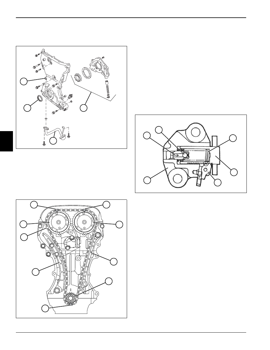
Front Cover
Figure 4-7
The front cover (1) houses the crankshaft-driven oil pump
(2) and front seal (3). Attached to the bottom of the cover
is the pickup strainer (4) for the oil pump.
Timing Chain
Figure 4-8
For the camshaft drive, a highly durable chain drive
system is used.
Through the timing chain (1), the crankshaft rotation is
transmitted from the crankshaft timing sprocket (7) to the
camshaft timing sprockets (2 and 5) installed on the end
of the intake and exhaust camshafts.
The timing chain has aligning links (3, 4, and 8) that are
used for aligning with the timing marks on the respective
camshaft sprockets and crankshaft sprocket.
A chain guide (6) and chain tensioner (9) system are
used to ensure quiet and accurate operation.
Tension Adjuster
Figure 4-9
The tension adjuster (6) has a plunger (4) inside, which
pushes against the tensioner link to give proper tension.
This plunger is operated by engine oil pressure (1) as
well as spring tension (3). The plunger is designed to
travel in only one way. Once the plunger has moved
outward, it will not come back due to the function of the
ratcheting mechanism (5).
There is a check ball (2) inside the plunger (4), which
keeps hydraulic pressure from dropping. With this
provision, the plunger can resist and absorb a kickback
force. During operation under low oil pressure, the ratchet
keeps the plunger from being pushed back, allowing
tension of the chain to be maintained. The result is quiet
operation without chain flapping.
TN0749
1
4
2
3
TN0502
1
2
3
4
5
6
7
8
9
TN0503
1
2
3
4
5
6
Нет комментариевНе стесняйтесь поделиться с нами вашим ценным мнением.
Текст