Suzuki: Engine K6A-YH6. Manual — part 13
7-6
REPAIR
7
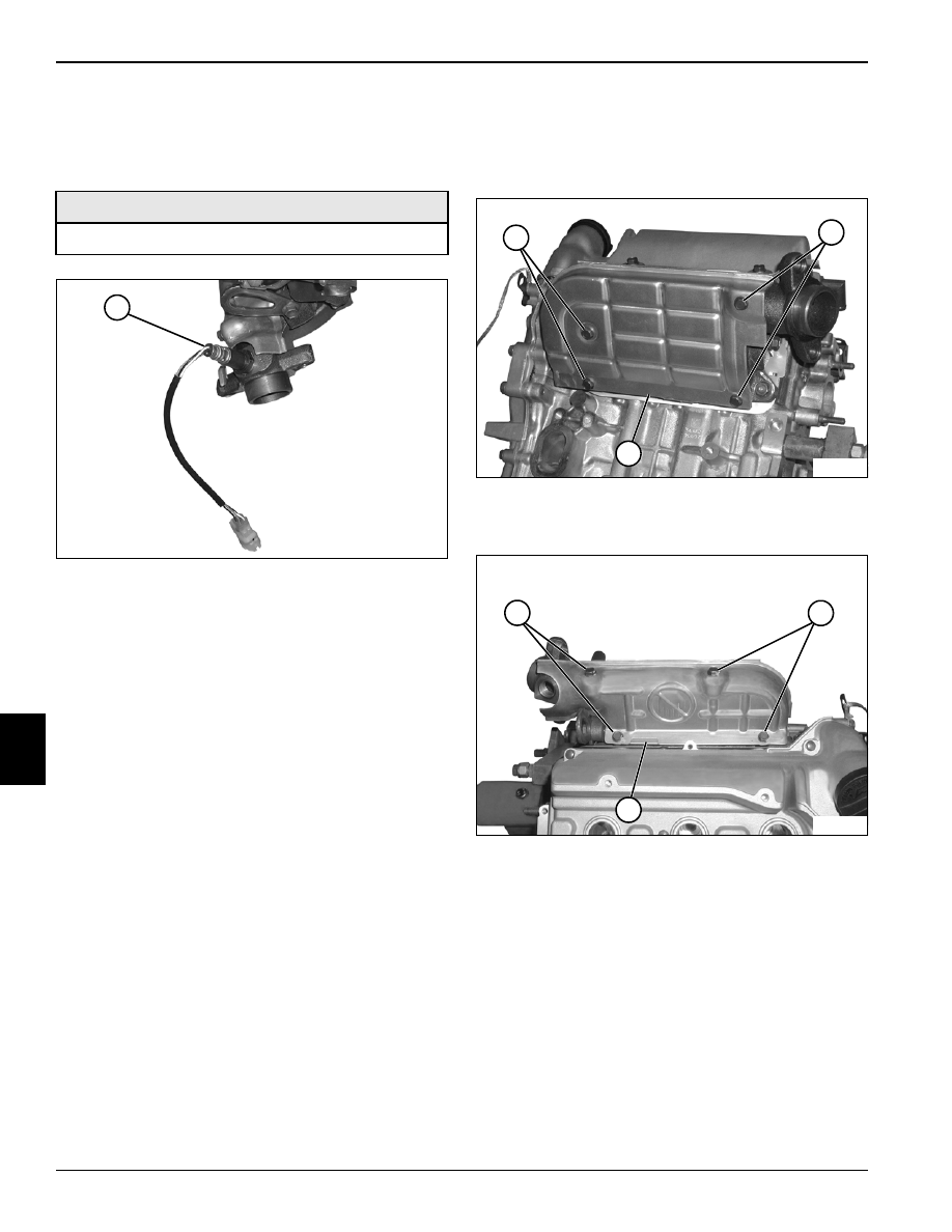
Oxygen Sensor
Removal and Installation
Figure 7-11
1.
Remove oxygen sensor (1).
2.
Inspect oxygen sensor. Replace as needed.
Installation Notes
Apply Anti-Seize Compound to the threads of oxygen
sensor before installation.
Install oxygen sensor by reversing the order of removal.
Heat Shield
Removal and Installation
Figure 7-12
1.
Remove cap screws (1) and lower half of heat shield
(2).
Figure 7-13
2.
Remove cap screws (3) and upper half of heat shield
(4).
Installation Note
Install heat shield by reversing order of removal.
Required Materials
Anti-Seize Compound
TN0699
1
TN0729
1
1
2
TN0730
3
3
4
REPAIR
7-7
7
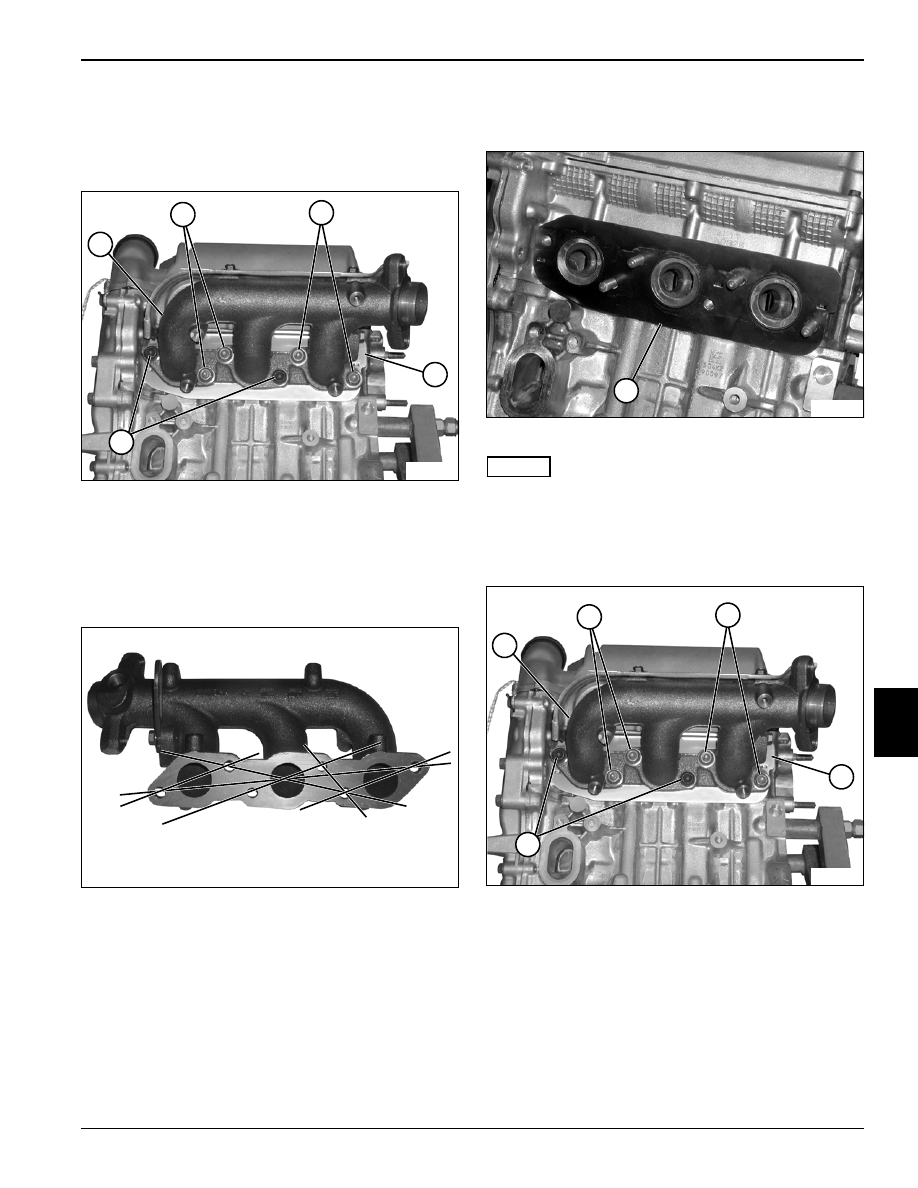
Exhaust Manifold
Removal
Figure 7-14
1.
Remove cap screws (4) and nuts (2).
2.
Remove exhaust manifold (1) and gasket (3).
Inspection
Figure 7-15
1.
Check exhaust manifold for cracks, damage, and
distortion.
2.
Using a straightedge and a feeler gauge, inspect the
mating face for distortion. Place the straightedge
across bolt hole centers at the locations indicated.
Measure any gaps with the feeler gauge. If the
measurement exceeds the limit, repair or replace
exhaust manifold.
Exhaust Manifold Distortion Limit: 0.003 in.
(0.07 mm)
Installation
Figure 7-16
NOTES
Clean exhaust manifold and cylinder head gasket
surfaces before installation.
Always use new O-rings, gaskets, and seals.
1.
Install new exhaust manifold gasket (1).
Figure 7-17
2.
Install exhaust manifold (2) using cap screws (5) and
nuts (3). Tighten to specification.
Exhaust Manifold Torque: 204 lb-in. (23 N•m)
Installation Note
Start engine and check for exhaust leaks.
TN0731
1
2
2
4
3
TN0734
TN0732
1
TN0731
2
3
3
5
4
7-8
REPAIR
7
7.2 Electrical System
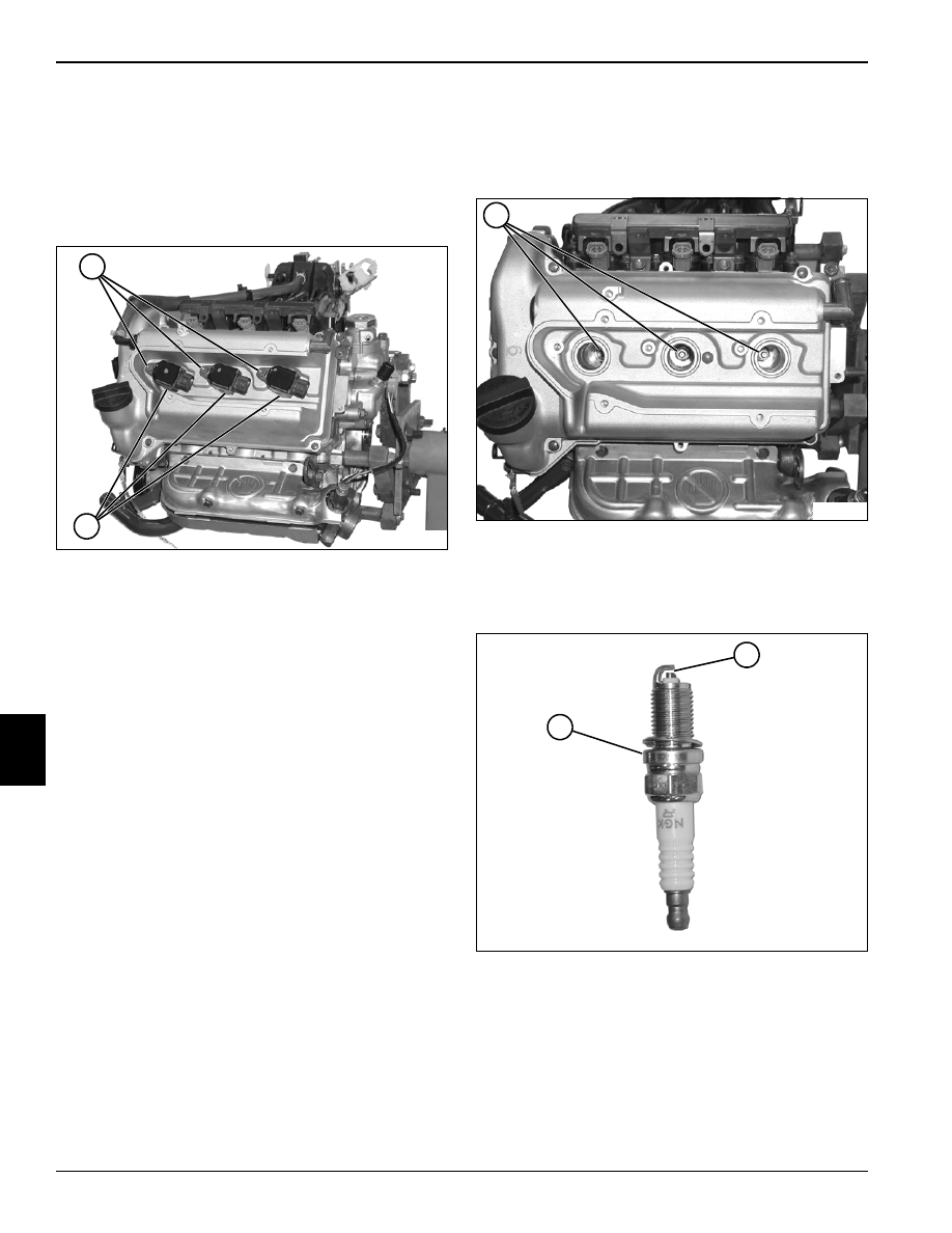
Ignition Coils
Removal and Installation
Figure 7-18
1.
Remove cap screws (1).
2.
Remove ignition coils (2).
3.
Inspect ignition coils. Replace as needed.
Installation Note
Install ignition coils by reversing the order of removal.
Spark Plugs
Removal and Installation
Figure 7-19
1.
Remove ignition coils. (See “Ignition Coils” on
page 7-8.)
2.
Remove spark plugs (1).
Figure 7-20
3.
Inspect spark plug (2) for signs of wear or damage.
Replace as needed.
4.
Set spark plug electrode gap (3) to specification.
Spark Plug Gap: 0.031—0.035 in. (0.8—0.9 mm)
Installation Note
Install spark plugs by reversing the order of removal.
TN0695
1
2
TN0697
1
TN0698
2
3
REPAIR
7-9
7
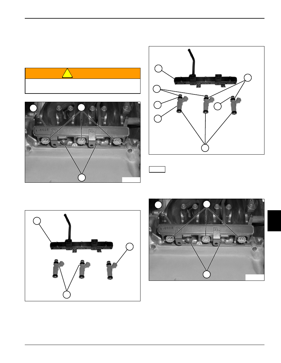
7.3 Fuel System
Injectors
Removal
!
WARNING
Figure 7-21
1.
Remove cap screws (3).
2.
Remove fuel rail (1) and injectors (2) as an assembly.
Figure 7-22
3.
Remove injectors (5) from fuel rail (4).
4.
Replace as needed.
Installation
Figure 7-23
NOTE
Always use new O-rings, gaskets, and seals.
1.
Install injectors (5) into fuel rail (1) using new O-rings
(3) and isolators (2 and 4).
Figure 7-24
2.
Install fuel rail (6) and injectors (7) as an assembly.
Secure with cap screws (8).
Fuel system may be under pressure. Relieve fuel
pressure before servicing system.
TN0738
1
2
3
TN0739
4
5
5
TN0739
5
1
4
3
2
3
2
TN0738
6
7
8
Нет комментариевНе стесняйтесь поделиться с нами вашим ценным мнением.
Текст