Suzuki Grand Vitara JB416 / JB420. Manual — part 335
9A-6 Wiring Systems:
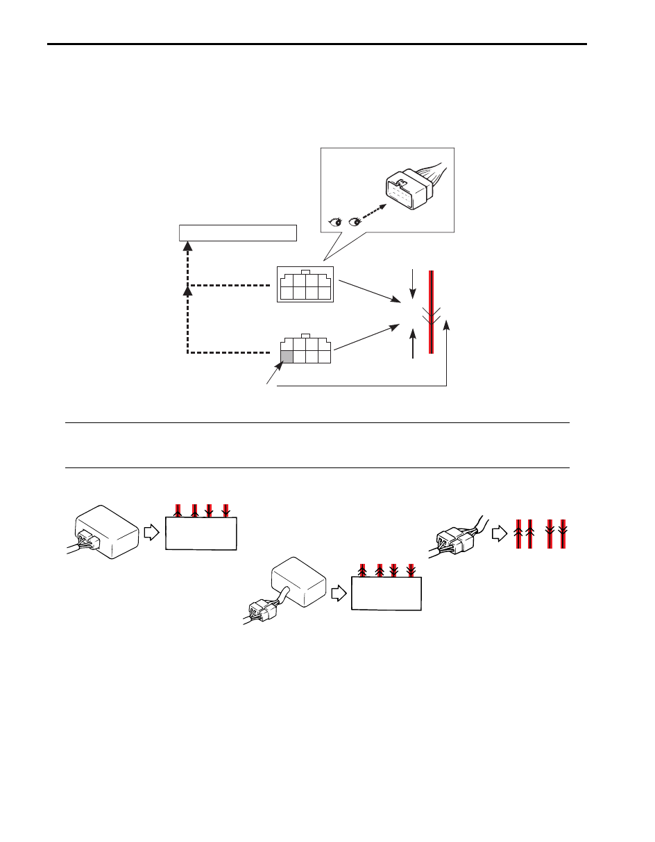
How to Read Connector Codes and Terminal Nos.
S5JB0A9101006
1) Connector code/Terminal No./Terminal layout
• The connector shape and terminal layout shown in this manual are those when viewed from “Z” in the
illustration.
Refer to “List of Connectors”.
NOTE
Molded terminal numbers that are different from the above can be found on some connectors in rare
cases.
These molded numbers are not applied in this manual.
2) Connector type
A40
(View Z)
(View Z)
1
1 2 3
4
5 6 7
8
2
3
4
5
6
7
8
D18
5
D18
A40
Connector code.
Connector code.
Terminal No.
"CONNECTOR LIST"
Male terminal
Female terminal
Z
View Z
I5RS0A910901-01
I2RH01910903-01
Wiring Systems: 9A-7
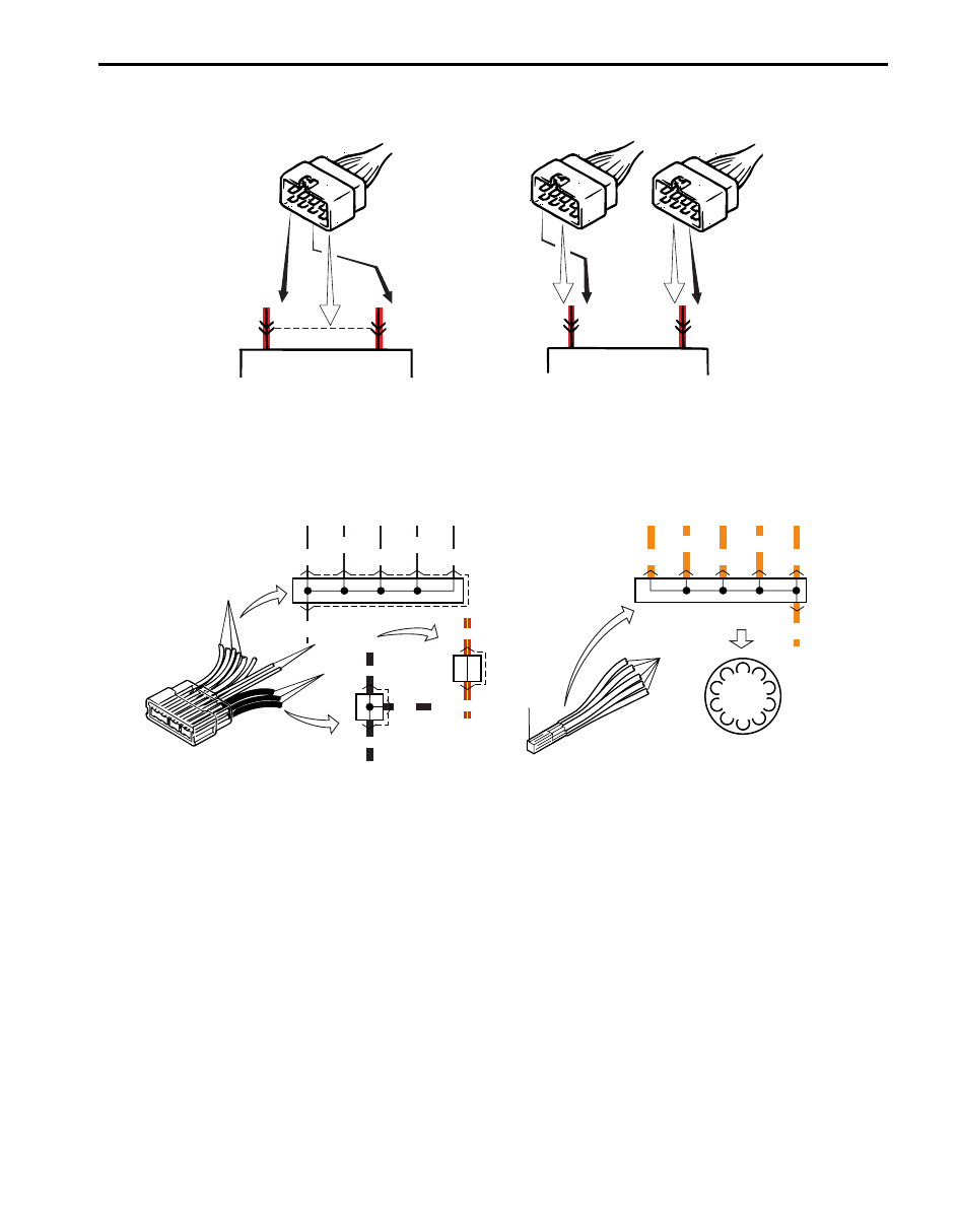
3) Terminals in one connector (Broken line) (B15)/Terminals in different connectors (B14, B16)
4) Joint connector (J/C)
• The joint connector (J/C) connects several different wires with the same wire color at one place instead of
connecting them by welding or caulking one by one. It is not an ordinary connector but a part of the continuous
wire in the harness.
B15
B15
B14
B16
5
7
B14
B16
5
7
I2RH01910904-01
BLK
BLK
A
A
A
B
B
RED/YEL
Weld
ORN
WHT/BLK
J/C
Weld splice
BLK
BLK
RED/YEL
RED/YEL
WHT/BLK
WHT/BLK
WHT/BLK
WHT/BLK
WHT/BLK
WHT/BLK
C
C
C
C
C
C
Weld
splice
(in Connector list)
J/C
ORN
ORN
ORN
ORN
ORN
ORN
Weld
splice
Example
I4RS0A910902-01
9A-8 Wiring Systems:
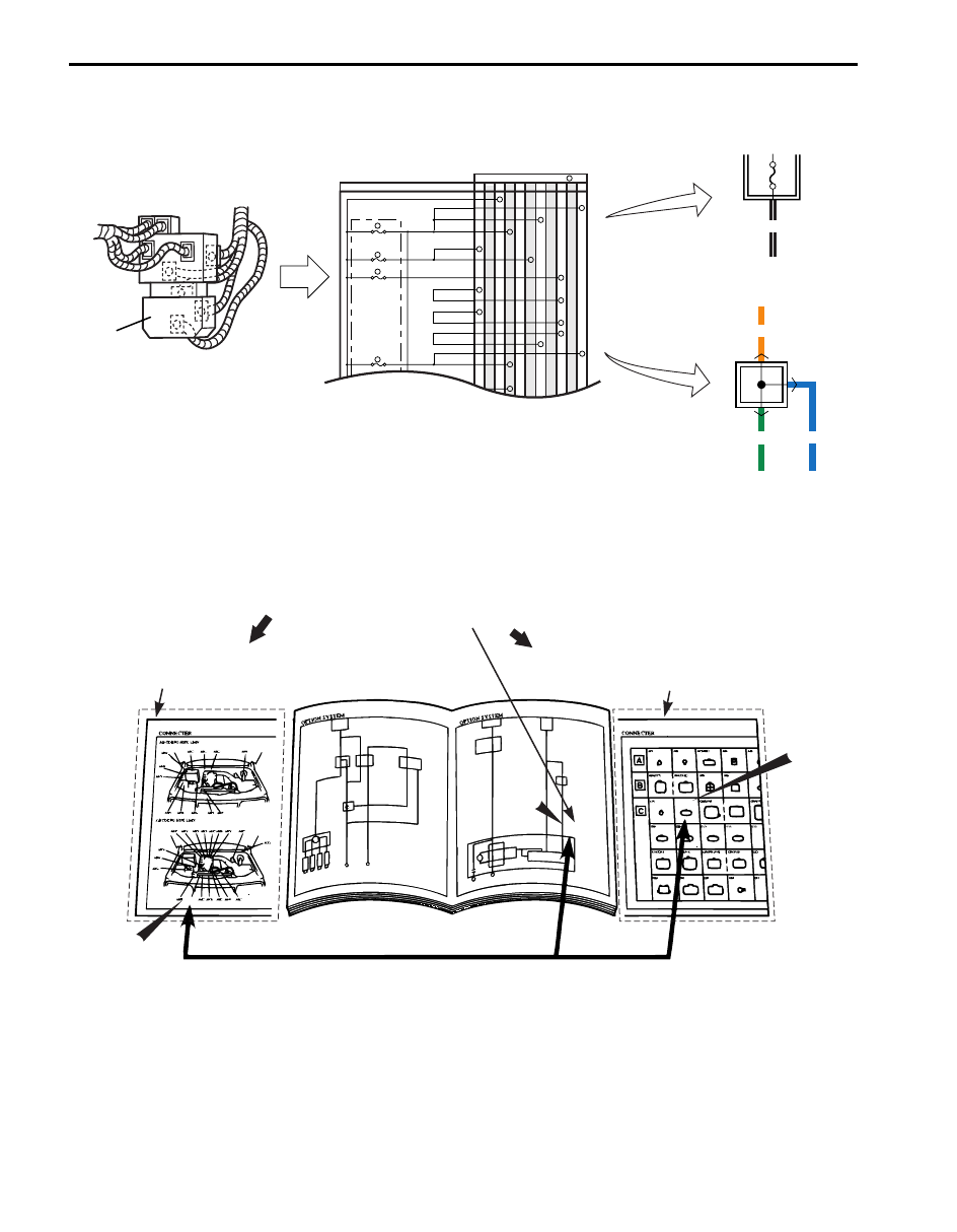
5) Junction block (J/B)
6) Connector location, shape and terminal No.
Refer to “Connector Layout Diagram”.
Refer to “System Circuit Diagram”.
Refer to “List of Connectors”.
IMMOBI IG
IG1
IG Coil, etc
E39
E41
E40
BCM
G34
G33
G32
K01 L04
L05
L06
IG Coil
IG1
15A
MTR
10A
A/B
15A
2
6
5
13
J/B
Connector No. / Terminal No.
BCM ;IG1
MTR Power, etc
A/B CONT
K-LINE
K-LINE
A/B SIGNAL
A/B SIGNAL
A/B SIG
A/B SIG
IG Sig
10A
EPS AT
MTA
4
6
1
3
2
4
8
11
9
12
9
11
23
25
30
29
Example
J/B
BLK/WHT
J/B
ORN
GRN
BLU
J/B
J/B inner circuit
I4RS0A910903-01
"SYSTEM CIRCUIT DIAGRAM"
-Connector code and terminal No.
"CONNECTOR LAYOUT DIAGRAM"
-Connector location.
CROSS-REFERENCE
"CONNECTOR LIST"
-Connector shape and terminal position.
C02
C02
C02
C02
C02
C02
I2RH01910906-01
Wiring Systems: 9A-9
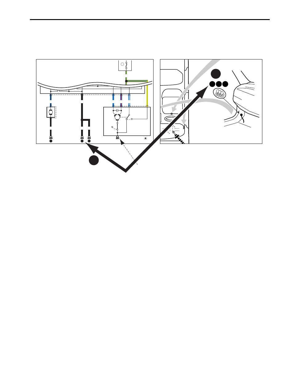
How to Read Ground Point
S5JB0A9101007
Refer to “System Circuit Diagram”.
Refer to “Ground (earth) Point”.
Left side shown
10 11 12
"SYSTEM CIRCUIT DIAGRAM"
"GROUND POINT"
CROSS-REFERENCE
Windoshield
washer
motor
Individual
circuit
fuse box
20
15A
Windoshield
wiper
motor
E40
E09
E20
16
2
1
Off
On
Circuit
breaker
60A-B003-
YEL/BLU
1
20
5
2
1
3
4
6
7
BLU/BLK
BLK
10
BLK
BLK
9
10
10
BLK
M
BLU
BLU/WHT
BLU/RED
M
Device body grounding is not given the ground point number.
I4JA01910985-01
Нет комментариевНе стесняйтесь поделиться с нами вашим ценным мнением.
Текст