Suzuki Grand Vitara JB416 / JB420. Manual — part 336

9A-10 Wiring Systems:
How to Read Power Supply Diagram
S5JB0A9101008
Refer to “Power Supply Diagram”.
Refer to “System Circuit Diagram”.
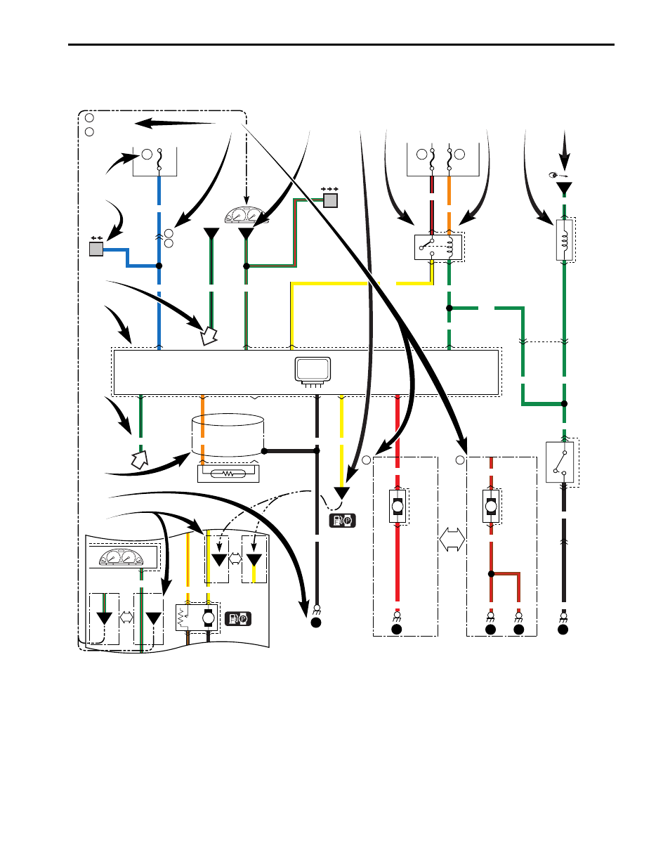
How to Read System Circuit Diagram
S5JB0A9101009
The circuit diagram is designed so the current flows from the top of the diagram (power source) to the bottom of the
diagram (ground) as if giving an image of water flow.
[A]: Fuse No.
[B]: Circuit jumping page / direction
NOTE
This means “Jump to the page directed with the arrow(s) by their number.
(For example:” Two arrows directing left” means” Jump to two pages before”.)
You will find the same symbol with the arrows directing opposite in the referenced page. The circuit
continues between the symbols.
[C]: Circuit jumping point / direction
NOTE
The circuit continues to the same symbol with opposite direction within the page.
You will find the other symbol in the direction of the arrow.
[D]: Terminals-in-one-connector mark
[E]: Wire color
[F]: Shield wire
[G]: Ground point
[H]: “From” or “To” (With ID letter (s))
[I]: Specification variation
The white arrow between A and B means “or”.
[J]: “From” (With ID letter (s))
[K] “To” (With ID letter (s))
[L]: Connector code
Connection to the system
indicated.
"POWER SUPPLY DIAGRAM"
-
+
1
Battery
80A
2
15A
3
15A
4
15A
5
25A
6
7
8
50A
30A
29
30A
32
15A
9
60A
60A
BLK
YEL/BLK
PNK/BLK
LT GRN
YEL/GRN
YEL/BLU
BLK/WHT
WHT/BLK
WHT/GRN
RED
GRN
WHT
WHT/BLU WHT/RED
WHT/BLU
WHT/YEL
WHT/GRN
WHT/GRN
WHT/GRN
BLU
BLU/RED
RED
YEL
BLU/RED
Individual
circuit
fuse box
Main fuse box
Supplementary fuse box
11
11
2
4
3
12 13 14 15 16 17 18
19 20
21
29
32
12
13
14
15
16
17
18
19
20
21
15A
15A
15A
20A
20A
15A
15A
15A
15A
15A
15A
E44
3
2
1
B01
1
E45
1
E40
2
1
Fuse
RED/YEL
YEL
WHT/GRN
15A
15A
13
17
"SYSTEM CIRCUIT DIAGRAM"
Fuse number
1
2
RY
I4JA01910986-01
Wiring Systems: 9A-11
[M]: Terminal No.
[N]: Symbol mark
[O]: “SEE” mark
Switch
BLU
BLU
GRN/BLK
GRN/RED
GRN/BLK
1
2
GRN
GRN
C26
2
1
BLK
5
BLK
2
1
C40
GRN/BLK
"XX"
Solenoid
Fuse
Fuse
3
15A
Main
relay
ON
OFF
1
15A
6
20A
1
Sensor
1
2
8
BRN/RED
E52
1
2
E52
1
BRN/RED
RED
2
BRN/RED BRN/RED
Motor
M
M
6
5
5
A
B
A
B
5
6
1
2
5
6
4
6
4
4-DOOR
2-DOOR
2
C71
E03
E34
O06
C31
E19
[A]
[B]
[C]
[F]
[G]
[H]
[D]
[I]
[K] [L]
E33
7
5
E34
1
2
1
4
3
E08
ORN
WHT
YEL
RED
YEL
YEL/RED
GRN/RED
4
3
YEL
BLK/RED
ORN
GRN
GRN
B
A
GRN
GRN
2
XX
Cont.M
[J]
[E]
[N]
[O]
[M]
GB
GR
Y
Y
GB
P
3
4
2
3
L50
G20
1
GR
Y
BLK
BLK
GR
I4JA01910987-01

9A-12 Wiring Systems:
Connector Layout Diagram
Connector Layout Diagram
S5JB0A910A006
Refer to “Engine Compartment”.
Refer to “Instrument Panel”.
Refer to “Door, Roof”.
Refer to “Floor”.
Refer to “Rear”.
Engine Compartment
S5JB0A910A001
C: Engine harness (M16A RHD)
C: Engine harness
C34
(TO E54)
C35
(TO E55)
1
5
4
3
C03
C01
C31
C02
C30
C10
C08
C09
C55
C07
C47
C56
C23
C24
2
C12
C06
C11
C22
C14
C21
C20
C26
C05
C04
C40
C41
C33
C19
C17
C18
C37
C13
C36
C15
C32
C
I5JB0A910901-05
No./Color
Connective position
No./Color
Connective position
C01/-
Battery (-)
C21/GRN Generator #1
C02/-
Battery fuse box
C22/-
Generator #2
C03/-
Fuse box No.1
C23/BLK
Starting motor #1
C04/GRY Injector #1
C24/-
Starting motor #2
C05/GRY Injector #2
C26/GRY Knock sensor
C06/GRY Injector #3
C30/BLK
(M/T)
Back-up light switch
C07/GRY Injector #4
C31/-
Battery fuse box
C08/BLK
CMP sensor
C32/-
Fuse box No.1
C09/BLK
ECT sensor
C33/N
P/S pump pressure switch
C10/GRY EGR stepper motor
C34/N
Main harness (To E54)

Wiring Systems: 9A-13
C: Engine harness (M16A LHD)
C: Engine harness
C11/BLK
Throttle position sensor
C35/BLU
Main harness (To E55)
C12/BLK
MAP sensor
C36/GRY A/F sensor
C13/BLK
MAF sensor
C37/GRY ECM
C14/BLK
EVAP canister purge valve
C40/GRY IG coil #1 & #4
C15/N
Rear heated oxygen sensor
C41/GRY IG coil #2 & #3
C17/BLK
A/C compressor
C47/BLK
Noise filter
C18/N
Oil pressure sensor
C55/-
Weld splice
C19/BLU VVT solenoid
C56/-
Weld splice
C20/N
CKP sensor
No./Color
Connective position
No./Color
Connective position
C34
(TO E54)
C35
(TO E55)
1
3
2
5
4
C03
C01
C31
C02
C30
C10
C08
C09
C55
C07
C47
C56
C23
C24
C12
C06
C11
C22
C14
C21
C20
C26
C05
C04
C40
C41
C33
C19
C17
C18
C37
C13
C36
C15
C32
C
I5JB0A910902-05
No./Color
Connective position
No./Color
Connective position
C01/-
Battery (-)
C21/GRN Generator #1
C02/-
Battery fuse box
C22/-
Generator #2
C03/-
Fuse box No.1
C23/BLK
Starting motor #1
C04/GRY Injector #1
C24/-
Starting motor #2
C05/GRY Injector #2
C26/GRY Knock sensor
C06/GRY Injector #3
C30/BLK
(M/T)
Back-up light switch
C07/GRY Injector #4
C31/-
Battery fuse box
C08/BLK
CMP sensor
C32/-
Fuse box No.1
C09/BLK
ECT sensor
C33/N
P/S pump pressure switch
C10/GRY EGR stepper motor
C34/N
Main harness (To E54)
C11/BLK
Throttle position sensor
C35/BLU
Main harness (To E55)
Нет комментариевНе стесняйтесь поделиться с нами вашим ценным мнением.
Текст