Suzuki Grand Vitara JB416 / JB420. Manual — part 176

3C-18 Transfer: Motor-Shift Type (Transfer with Shift Actuator)
d) Turn transfer switch to “4H-lock” position.
e) Check that differential lock indicator blinks, and
then comes ON steady.
2) Inspect shift operation from 4H-lock to 4L-lock as
follows.
a) Stop vehicle completely with engine running.
b) Position front wheels straight ahead.
c) Confirm that vehicle is under following
conditions.
• Transfer shift position is 4H-lock.
• Transmission shift lever is at “N” position. (for
A/T model)
• Clutch pedal is depressed fully. (for M/T
model)
• Brake pedal is depressed.
d) Push and turn transfer switch to “4L-lock”
position.
e) Check that 4L indicator blink, and then
differential lock indicator and 4L indicator comes
ON steady.
3) Inspect shift operation from 4L-lock to 4H-lock as
follows.
a) Stop vehicle completely with engine running.
b) Position front wheels straight ahead.
c) Confirm that vehicle is under following
conditions.
• Transfer shift position is 4L-lock.
• Transmission shift lever is at “N” position. (for
A/T model)
• Clutch pedal is depressed fully. (for M/T
model)
• Brake pedal is depressed.
d) Push and turn transfer switch to “4H-lock”
position.
e) Check that 4L indicator blink, and then
differential lock indicator comes ON steady and
4L indicator not come ON.
4) Inspect shift operation from 4H-lock to 4H as follows.
a) Start engine.
b) Position front wheels straight ahead.
c) Confirm that vehicle is under following
conditions.
• Transfer shift position is 4H-lock.
• Vehicle speed is less than 100 km/h (60 mph).
d) Turn transfer switch to “4H” position.
e) Check that differential lock indicator blinks, and
then not comes ON.
5) Inspect shift operation from 4H to N as follows.
a) Stop vehicle completely with engine running.
b) Position front wheels straight ahead.
c) Confirm that vehicle is under following
conditions.
• Transfer shift position is 4H.
• Transmission shift lever is at “N” position. (for
A/T model)
• Clutch pedal is depressed fully. (for M/T
model)
• Brake pedal is depressed.
d) Turn transfer switch to “” position (1), keep it
there for about 10 seconds, and then turn it to
“N” position after N indicator blinks.
e) Check that N indicator blinks and warning buzzer
sounds, and then N indicator comes ON steady.
Visual Inspection
S5JB0A3314005
Check the following parts and systems visually.
1
I5JB0A332002-01
Inspection Item
Referring
• Front differential oil ---- level, leakage
“Front Differential Oil Change: Front in Section 3B”
• Rear differential oil ---- level, leakage
“Rear Differential Oil Change: Rear in Section 3B”
• Transfer gear oil ---- level, leakage
“Transfer Oil Change: Motor-Shift Type (Transfer with
Shift Actuator)”
• Manual transmission oil ---- level, leakage
“Manual Transmission Oil Change in Section 5B”
• A/T fluid ---- level, leakage
“A/T Fluid Level Check in Section 5A”
• Transfer mounting(s) ---- wear and looseness
• Fuses ---- burning
• Battery ---- fluid level, corrosion of terminal
“Battery Inspection in Section 1J”
• Connectors of electric wire harness ---- disconnection,
friction
“Intermittent and Poor Connection Inspection in Section
00”
• Other parts that can be checked visually
Transfer: Motor-Shift Type (Transfer with Shift Actuator) 3C-19
DTC Check
S5JB0A3314006
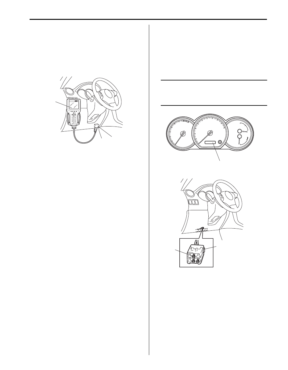
Using SUZUKI Scan Tool
1) Turn ignition switch to OFF position.
2) Connect SUZUKI scan tool to data link connector
(DLC) (1) located on underside of instrument panel.
Special tool
(A): SUZUKI scan tool
3) Turn ignition switch to ON position.
4) Read DTC according to instructions displayed on
SUZUKI scan tool and print it or write it down. Refer
to SUZUKI scan tool operator’s manual for further
details.
If communication between SUZUKI scan tool and
4WD control module is not possible, check if
SUZUKI scan tool is communicable by connecting it
to 4WD control module in another vehicle. If
communication is possible in this case, SUZUKI
scan tool is in good condition. Then check data link
connector and serial data line (circuit) in the vehicle
with which communication was not possible.
5) After completing the check, turn ignition switch OFF
and disconnect SUZUKI scan tool from data link
connector (DLC).
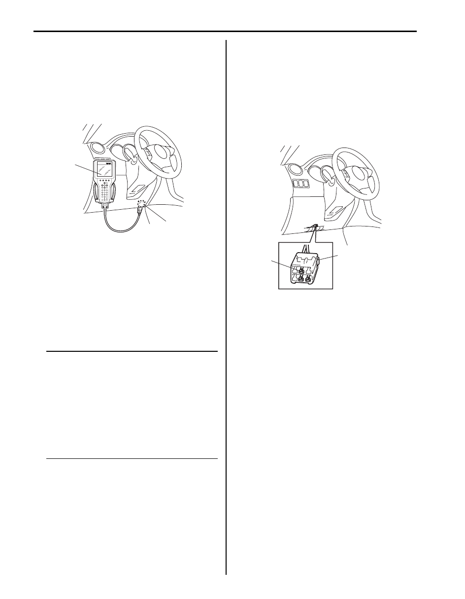
Using Diagnosis Connector
1) With ignition switch OFF position, using service wire
short diagnosis switch terminal (1) of diagnosis
connector (2) and body ground.
2) With ignition switch ON position and leaving engine
OFF, read DTC displayed on digital display odometer
(3) of combination meter referring to “DTC Table:
Motor-Shift Type (Transfer with Shift Actuator)”.
NOTE
When more than 2 DTCs are stored in
memory, flashing for each DTC is repeated
three times starting with the smallest DTC
number in increasing order.
3) After completing the check, turn ignition switch OFF,
disconnect service wire from diagnosis connector.
(A)
1
I5JB0A332012-01
1
2
3
I5JB0A332013-01
3C-20 Transfer: Motor-Shift Type (Transfer with Shift Actuator)
DTC Clearance
S5JB0A3314007
Using SUZUKI Scan Tool
1) Turn ignition switch to OFF position.
2) Connect SUZUKI scan tool to data link connector
(DLC) (1) located on underside of instrument panel.
Special tool
(A): SUZUKI scan tool
3) Turn ignition switch to ON position.
4) Erase DTC according to instructions displayed on
SUZUKI scan tool. Refer to SUZUKI scan tool
operator’s manual for further details.
5) After completing clearance, turn ignition switch OFF
and disconnect SUZUKI scan tool from data link
connector (DLC).
6) Perform “DTC Check: Motor-Shift Type (Transfer
with Shift Actuator)” and confirm that NO CODES is
displayed.
NOTE
DTC and freeze frame data stored in 4WD
control module memory are also cleared in
the following cases. Be careful not to clear
them before keeping their record.
• When power to 4WD control module is cut
off (by disconnecting battery cable,
removing fuse or disconnecting 4WD
control module connectors).
• When the same malfunction (DTC) is not
detected again during 40 engine warm-up
cycles.
Using Diagnosis Connector
1) Turn ignition switch to ON position.
2) Using service wire short diagnosis switch terminal
(1) of diagnosis connector (2) and body ground more
than 5 times at about 1 second interval within 10
seconds.
3) Wait more than 9 seconds.
4) Perform “DTC Check: Motor-Shift Type (Transfer
with Shift Actuator)” and confirm that DTC No. is not
displayed.
(A)
1
I5JB0A332012-01
1
2
I5JB0A332014-01
Transfer: Motor-Shift Type (Transfer with Shift Actuator) 3C-21
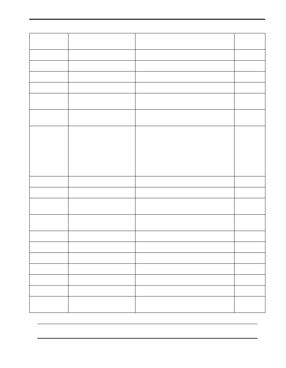
DTC Table
S5JB0A3314008
NOTE
“O” in transfer position indicator column of the above table means indicator lights up when DTC is
detected.
DTC No.
Detecting item
Detecting condition
(DTC will set when detecting)
Transfer
position
indicators
Transfer switch circuit open
Different switch combination from specification is
detected.
{
Transfer switch circuit short
Different switch combination from specification is
detected.
{
Transfer shift actuator motor
position switch 1 circuit open
Actuator position switch signal voltage 4.2 V or
more.
{
Transfer shift actuator motor
position switch 1 circuit short
Actuator position switch signal voltage 0.6 V or
less.
{
4L/N switch circuit open
Though actuator position switch is “4L-lock”
position, the ON signal is not input from the 4L/N
switch.
{
4L/N switch circuit short
Though actuator position switch is “4L-lock”
position, the OFF signal is not input from the 4L/
N switch.
{
Transfer actuator circuit
malfunction
• Position switch in transfer shift actuator is not
changed for 3 seconds even if command
signal of motor relay for transfer shift actuator
(included in 4WD control module) is turned on.
or
• Monitor signal from motor relay of transfer
shift actuator (included in 4WD control
module) is inconsistent with command signal
to motor relay of transfer shift actuator.
{
Transfer shift actuator motor
position switch 2 circuit open
Actuator position switch signal voltage 4.2 V or
more.
{
Transfer shift actuator motor
position switch 2 circuit short
Actuator position switch signal voltage 0.6 V or
less.
{
Center differential lock switch
circuit open
Though actuator position switch is “4H” position,
the ON signal is not input from the center
differential lock switch.
{
Center differential lock switch
circuit short
Though actuator position switch is “4L-lock”
position, the OFF signal is not input from the
center differential lock switch.
{
4WD control module power
supply circuit malfunction
Battery voltage is lower than lower limit voltage
for 4WD control module diagnosis.
{
Internal circuit malfunction of
4WD control module
EEPROM error
{
Clutch pedal position (CPP)
switch circuit short
CPP switch signal is input when vehicle speed is
30 km/h (19 mph).
{
Control module communication
bus off
Transmitting and receiving error of 4WD control
module for specified time continuously.
{
U1100
Lost communication with ECM
Receiving error of 4WD control module from
ECM for specified time continuously.
{
U1101
Lost communication with TCM
Receiving error of 4WD control module from
TCM for specified time continuously.
{
U1121
Lost communication with ABS
control module
Receiving error of 4WD control module from
ABS control module for specified time
continuously.
{
Нет комментариевНе стесняйтесь поделиться с нами вашим ценным мнением.
Текст