Suzuki Grand Vitara JB416 / JB420. Manual — part 174
3C-10 Transfer: Motor-Shift Type (Transfer with Shift Actuator)
On-Board Diagnostic System Description
S5JB0A3311009
For 4WD control system, 4WD control module has the following functions.
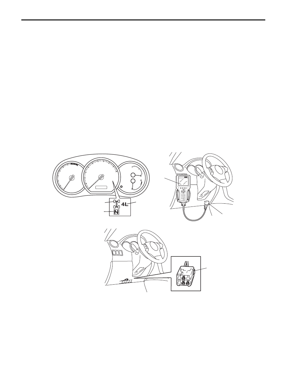
• When ignition switch is turned ON with engine at stop, differential lock indicator (1), 4L indicator (2) and N indicator
(3) turn on at the same time for 2 seconds in order to check operation of these indicators.
• When 4WD control module detects any malfunction in the following area, differential lock indicator (1), 4L indicator
(2) and N indicator (3) flash continuously and 4WD control module comes into fail-safe mode. For details of fail safe
mode, refer to “Fail-Safe Table: Motor-Shift Type (Transfer with Shift Actuator)”.
– Transfer switch
– Transfer shift actuator motor
– Transfer shift actuator motor position switch
– 4L/N switch
– Center differential lock switch
• DTC can be checked by either one of the following ways.
– DTC can be checked by using SUZUKI scan tool (4) connected to DLC (5).
– If equipped with diagnosis connector, DTC can be displayed on digital display odometer by shorting diagnosis
connector (6).
• When 4WD control module detects any malfunction, 4WD control module will shift automatically transfer to either N
or former position which is in before shifting process began.
DLC (Data Link Connector)
Refer to “Data Link Connector (DLC)” under “On-Board Diagnostic System Description in Section 1A”.
1
2
3
4
5
6
I5JB0A332008-01
Transfer: Motor-Shift Type (Transfer with Shift Actuator) 3C-11
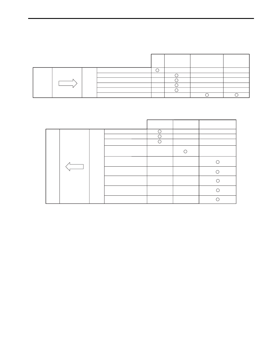
CAN Communication System Description
S5JB0A3311011
Refer to “CAN Communication System Description in Section 1A”.
4WD Control Module Transmission Data
4WD Control Module Reception Data
BCM
Combination
Meter
Transmit
DATA
4WD
Buzzer on reques
Lock indication status
Neutral Indication Status
Low indication status
4WD diagnostic trouble codes
control
module
ABS control
module
(Non-ESP® model)
ESP® control
module
(ESP® model)
4WD shift position
I5JB0A332010-02
ECM
TCM
DATA
Receive
Engine speed
Vehicle speed
Brake pedal switch active
4WD
control
module
Transmission gear
selector position
Wheel speed pulse
(front right)
Wheel speed pulse
(front left)
Wheel speed pulse
(rear right)
Wheel speed pulse
(rear left)
Antilock brake system
active
ABS hydraulic unit /
control module
I5JB0A332009-01

3C-12 Transfer: Motor-Shift Type (Transfer with Shift Actuator)
Schematic and Routing Diagram
4WD Control System Wiring Circuit Diagram
S5JB0A3312001
5V
5V
IG
5V
12V
E91-2
5V
12V
12V
+BB
YEL
RED/BLK
BLU
M
E91-3
E91-25
E91-26
RED
E91-24
BLK/YEL
E91-7
BLK/ORN
E91-21
PPL/WHT
E91-22
E91-23
RED
WHT
E91-18
E91-19
E91-20
E91-13
E91-14
E91-12
E91-11
E91-10
E91-1
BLK
BLK
WHT
BLK/WHT
RED/GRN
PNK/WHT
BLU/ORN
BLU/BLK
LT GRN
12V
12V
G59-2
G59-3
G59-4
C54-1
C54-4
C54-2
C54-3
C54-5
WHT/RED
WHT/BLU
1
2
3
4
5
6
7
8
9
10
12
11
13
14
15
17
18
19
20
21
23
22
16
E91-8
PNK
I5JB0A332007-03
1. Transfer actuator
9. ABS hydraulic unit/control module
17. DLC
2. Transfer actuator position switch
10. ECM
18. “IG COIL” fuse
3. Transfer actuator motor
11. 4WD control module
19. Ignition switch
4. CPP switch (for M/T model)
12. Transfer switch
20. “4WD” fuse
5. BCM
13. TCM (for A/T model)
21. Shift switch (for A/T model) or CPP switch (for M/T model)
6. TCM (for A/T model)
14. 4L/N switch
22. Main fuse box
7. Combination meter
15. Center differential lock switch
23. Starting motor
8. Keyless start control module (if equipped)
16. Diagnosis connector (if equipped)
Transfer: Motor-Shift Type (Transfer with Shift Actuator) 3C-13
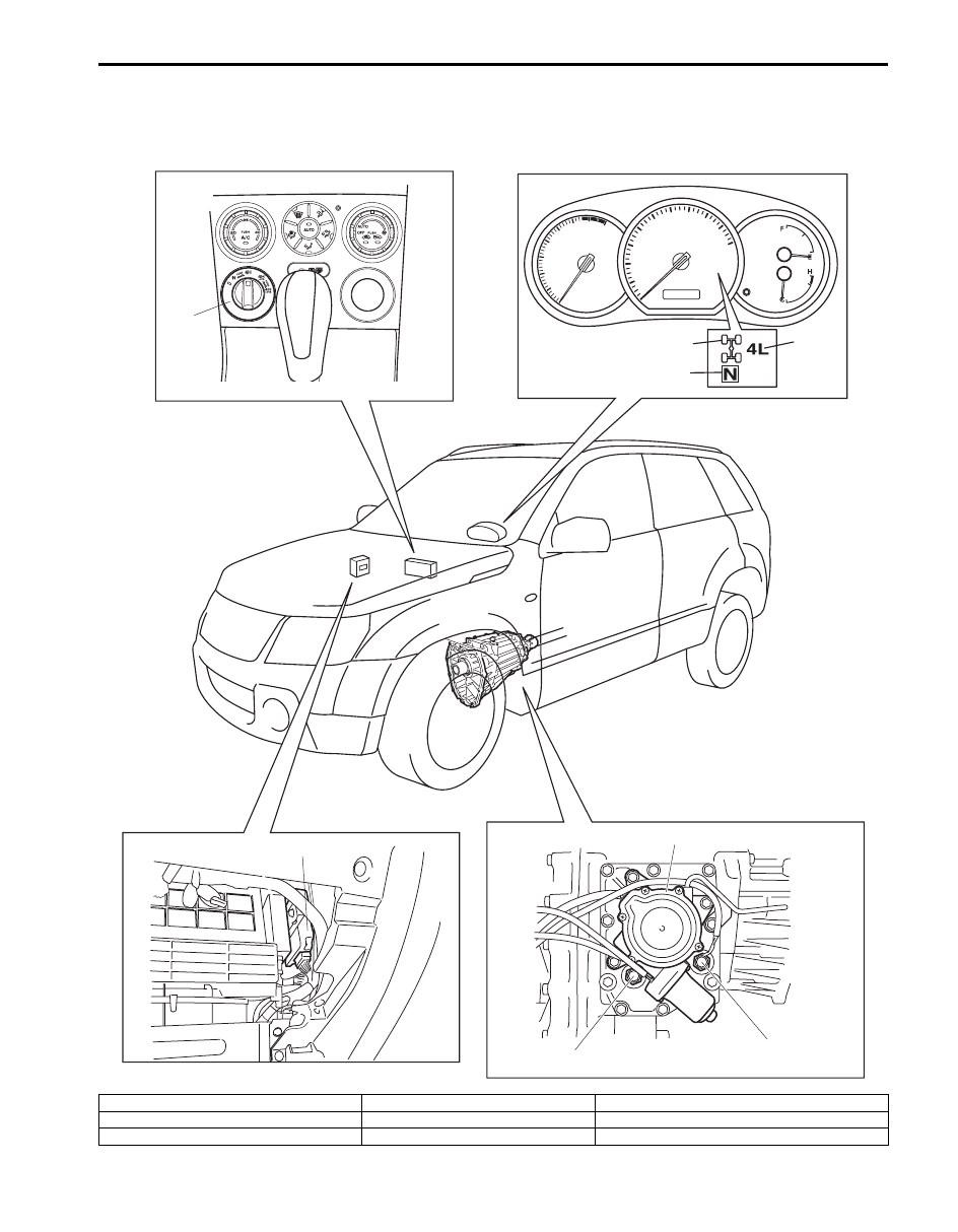
Component Location
Transfer Shift Control System Components
S5JB0A3313001
6
7
5
1
8
2
3
4
I5JB0A332001-01
1. Transfer switch
4. N indicator
7. Center differential lock switch
2. Differential lock indicator
5. 4WD control module
8. 4L/N switch
3. 4L indicator
6. Transfer actuator
Нет комментариевНе стесняйтесь поделиться с нами вашим ценным мнением.
Текст