Suzuki Grand Vitara JB416 / JB420. Manual — part 135
1I-8 Starting System:
Brush Spring
Inspect brush springs for wear, damage or other
abnormal conditions. Replace if necessary.
Brush spring tension
Standard: 1.8 kg (3.97 lb)
Limit: 0.3 kg (0.67 lb)
Brush Holder
• Check movement of brush in brush holder. If brush
movement within brush holder is sluggish, check
brush holder for distortion and sliding faces for
contamination. Clean or correct as necessary.
• Check for continuity across insulated brush (positive
side) and grounded brush (negative side). If continuity
exists, brush holder is grounded due to defective
insulation and should be replaced.
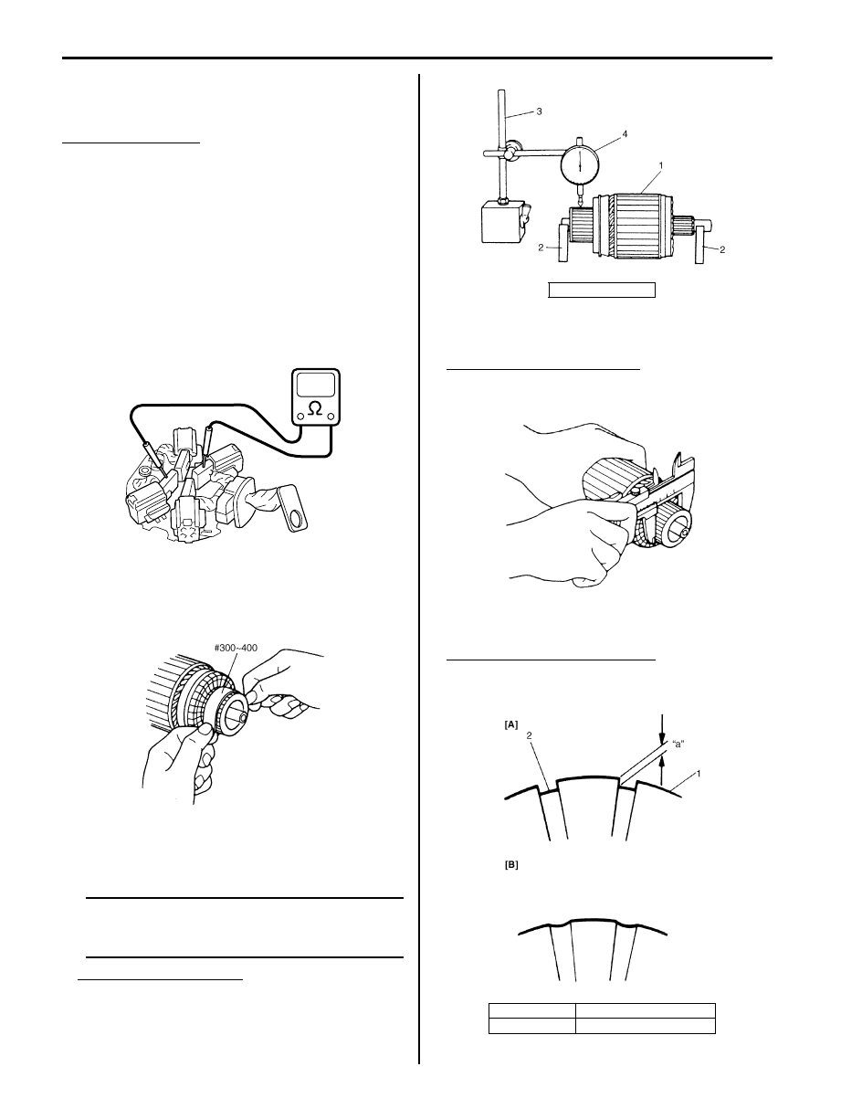
Armature
• Inspect commutator for dirt or burn. Correct with
sandpaper or lathe, if necessary.
• Check commutator for uneven wear with armature (1)
supported on V-blocks (2). If deflection of dial gauge
(4) pointer exceeds limit, repair or replace.
NOTE
The following specification presupposes that
armature is free from bend. Bent armature
must be replaced.
Commutator out of round
Standard: 0.05 mm (0.002 in.) or less
Limit: 0.4 mm (0.016 in.)
• Inspect commutator for wear. If diameter is below
limit, replace armature.
Commutator outside diameter
Standard: 29.4 mm (1.16 in.)
Limit: 28.8 mm (1.13 in.)
• Inspect commutator for insulator depth. Correct or
replace if below limit.
Commutator insulator depth “a”
Standard: 0.4 – 0.6 mm (0.016 – 0.024 in.)
Limit: 0.2 mm (0.008 in.)
I4RS0A190004-01
IYSQ01190034-01
3. Magnetic stand
[A]: Correct
1. Commutator segment
[B]: Incorrect
2. Insulator
IYSQ01190035-01
IYSQ01190036-01
I5JB0A190003-01
Starting System: 1I-9
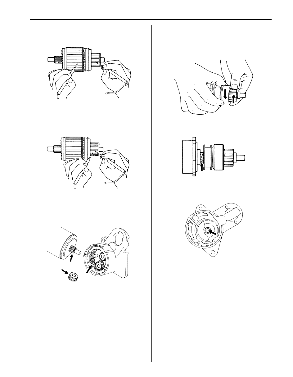
Ground test
Check the commutator and armature core. If there is
continuity, armature is grounded and must be replaced.
Open circuit test
Check for continuity between segments. If there is no
continuity at any test point, there is an open circuit and
the armature must be replaced.
Gears
Inspect internal gear and the planetary gears for wear,
damage or other abnormal conditions. Replace if
necessary.
Pinion and Over-Running Clutch
• Inspect pinion for wear, damage or other abnormal
conditions. Check that clutch locks up when turned in
direction of drive and rotates smoothly in reverse
direction. Replace if necessary.
• Inspect spline teeth for wear or damage. Replace if
necessary. Inspect pinion for smooth movement.
Front Housing Bush
Inspect bush for wear or damage. Replace if necessary.
IYSQ01190038-01
IYSQ01190039-01
IYSQ01190040-01
IYSQ01190041-01
IYSQ01190042-01
IYSQ01190043-01
1I-10 Starting System:
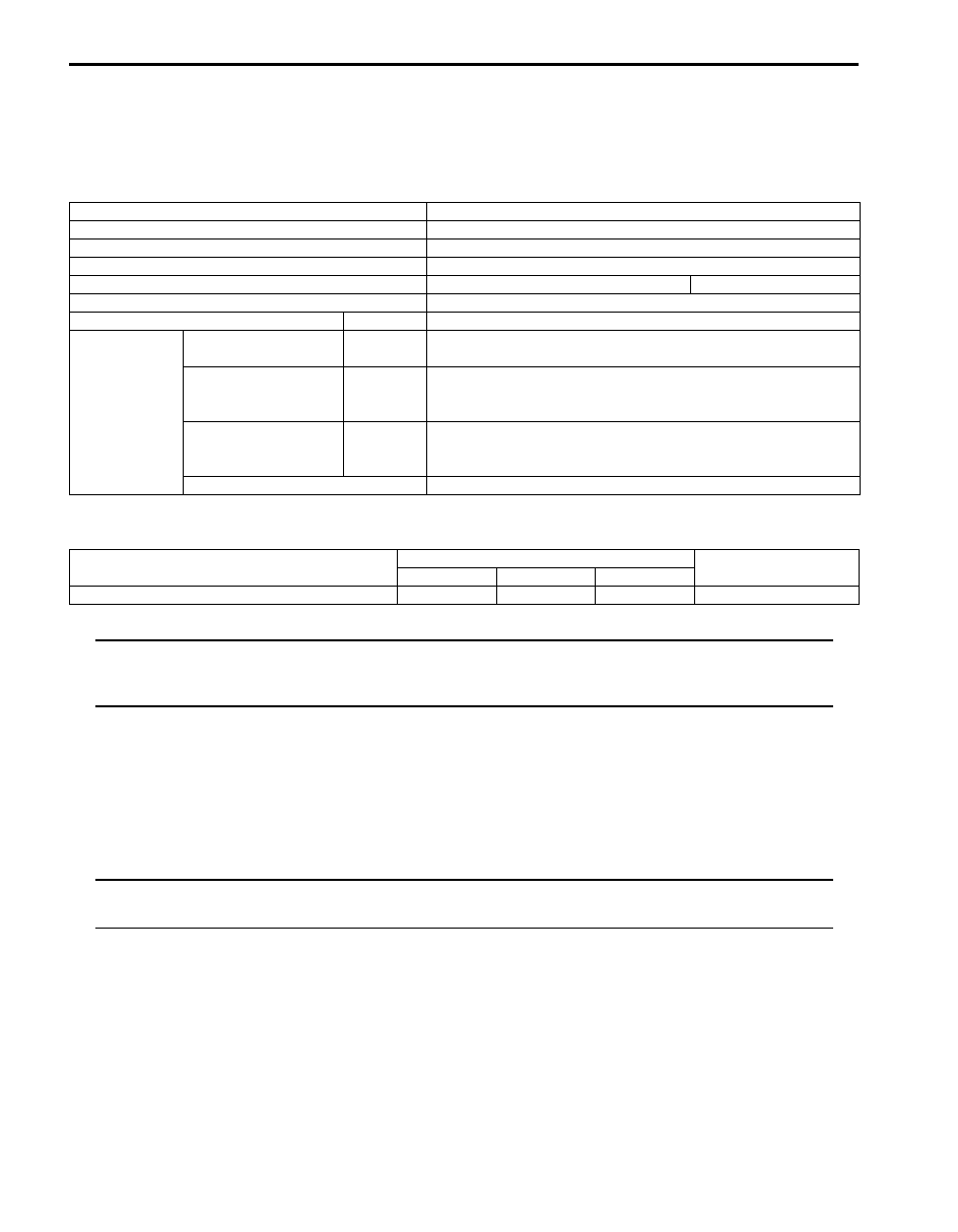
Specifications
Starting Motor Specifications
S5JB0A1907001
1.2 kW Type [1.4 kW Type]
Tightening Torque Specifications
S5JB0A1907002
NOTE
The specified tightening torque is also described in the following.
“Starting Motor Dismounting and Remounting”
“Starting Motor Components”
Reference:
For the tightening torque of fastener not specified in this section, refer to “Fastener Information in Section 0A”.
Special Tools and Equipment
Recommended Service Material
S5JB0A1908001
NOTE
Required service material is also described in the following.
“Starting Motor Components”
Voltage
12 volts
Output
1.2 kW [1.4 kW]
Rating
30 seconds
Direction of rotation
Clockwise as viewed from pinion side
Brush length
Standard: 12.3 mm (0.48 in.)
Limit: 5.5 mm (0.22 in.)
Number of pinion teeth
8
Performance
Condition
Guarantee
Around
at 20
°C (68 °F)
No load characteristic
11.0 V
90 A maximum
2370 r/min minimum [2000 r/min minimum]
Load characteristic
7.5 V
300 A
10.65 N
⋅m (1.065 kgf-m, 7.70 lb-ft) minimum
[11.0 N
⋅m (1.1 kgf-m, 7.95 lb-ft) minimum]
840 r/min minimum
Locked characteristic
4.0 V
[3.0 V]
780 A maximum
[860 A maximum]
20 N
⋅m (2.0 kgf-m, 14.5 lb-ft) minimum
Magnetic switch operating voltage 8 volts maximum
Fastening part
Tightening torque
Note
N
⋅m
kgf-m
lb-ft
Starting motor battery cable nut
11
1.1
8.0

Charging System: 1J-1
Engine
Charging System
General Description
Battery Description
S5JB0A1A01001
The battery has three major functions in the electrical system.
• It is a source of electrical energy for cranking the engine.
• It acts as a voltage stabilizer for the electrical system.
• It can, for a limited time, provide energy when the electrical load exceeds the output of the generator.
Carrier and Hold-Down
The battery carrier should be in good condition so that it will support the battery securely and keep it level.
Before installing the battery, the battery carrier and hold-down clamp should be clean and free from corrosion and
make certain there are no parts in carrier.
To prevent the battery from shaking in its carrier, the hold-down bolts should be tight enough but not over-tightened.
Electrolyte Freezing
The freezing point of electrolyte depends on its specific gravity. Since freezing may ruin a battery, it should be
protected against freezing by keeping it in a fully charged condition. If a battery is frozen accidentally, it should not be
charged until it is warmed.
Sulfation
If the battery is allowed to stand for a long period in discharged condition, the lead sulfate becomes converted into a
hard, crystalline substance, which will not easily turn back to the active material again during the subsequent
recharging. “Sulfation” means the result as well as the process of that reaction.
Such a battery can be revived by very slow charging and may be restored to usable condition but its capacity is lower
than before.
Built-in Indicator (if equipped)
The battery has a built-in temperature compensated indicator (1) in the top of the battery. This indicator is to be used
with the following diagnostic procedure.
When checking the indicator, make sure that the battery has a clean top. A light may be needed in some poorly-lit
areas.
Three types of indication available under normal operation are as follows.
IYSQ011A0001-01
Нет комментариевНе стесняйтесь поделиться с нами вашим ценным мнением.
Текст