Suzuki Grand Vitara JB416 / JB420. Manual — part 136
1J-2 Charging System:
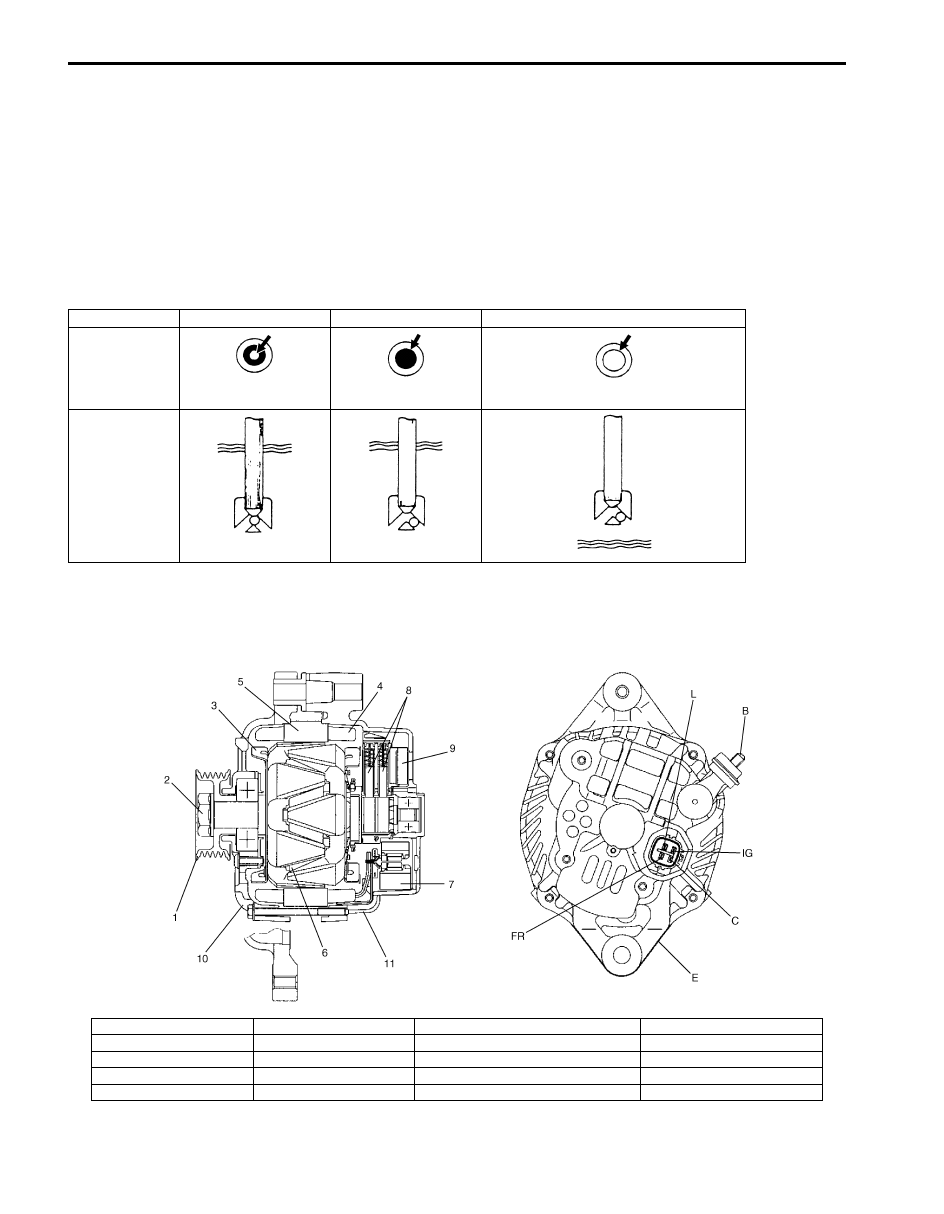
• Green Dot:
Battery is sufficiently charged for testing.
• Dark:
Battery must be charged before testing.
If there is a cranking complaint, battery should be tested as described in “Battery Inspection”.
Charging and electrical systems should also be checked at this time.
• Clear or Light Yellow:
This means that fluid level is below the bottom of hydrometer. Its possible cause is excessive or prolonged
charging, a broken case, excessive tipping or normal battery deterioration.
When the battery is found in such condition, it is possible that high charging voltage is caused by the faulty charging
system and therefore, charging and electrical systems need to be checked. If there is a trouble in cranking and its
cause lies in the battery, it should be replaced.
Generator Description
S5JB0A1A01002
The basic charging system is the IC integral regulator charging system. The internal components are connected
electrically as shown below.
Diagnosis
OK
Charging necessary Low Level Electrolyte Replace Battery
Indicator
Green dot
Dark
Clear
Gravity Ball
IYSQ011A0002-01
IYSQ011A0065-01
IYSQ011A0066-01
IYSQ011A0067-01
IYSQ011A0068-01
IYSQ011A0069-01
I5JB0A1A0004-01
1. Pulley
6. Field coil
11. Rear housing
IG: Ignition terminal
2. Pulley nut
7. Rectifier
B: Generator output (Battery terminal)
L: Lamp terminal
3. Rotor fan
8. Brush
C: Generator cut
4. Stator coil
9. Regulator
E: Ground
5. Stator core
10. Front housing
FR: Field duty monitor

Charging System: 1J-3
Charging System Circuit
The generator features a solid state regulator that is mounted inside the generator. All regulator components are
enclosed into a solid mold, and this unit along with the brush holder assembly is attached to the rear housing. The
regulator voltage is being controlled by ECM under some conditions while driving. Refer to “Generator Control System
Description in Section 1A”.
The generator rotor bearings contain enough grease to eliminate the need for periodic lubrication.
Two brushes carry current through the two slip rings to the field coil mounted on the rotor, and under normal conditions
will provide long period of attention-free service.
The stator windings are assembled inside a laminated core that forms part of the generator frame.
A rectifier bridge connected to the stator windings contains diodes, and electrically changes the stator AC. voltages to
a D.C. voltage which appears at the generator output terminal.
Diagnostic Information and Procedures
Battery Inspection
S5JB0A1A04004
Common Causes of Failure
A battery is not designed to last indefinitely; however, with proper care, it will provide many years of service. If the
battery performs satisfactorily during test but fails to operate properly for no apparent reason, the following are some
factors that may point to the cause of trouble:
• Accessories left on overnight or for an extended period without the generator operating.
• Slow average driving speeds for short periods.
• Electrical load exceeding generator output particularly with addition of aftermarket equipment.
• Defects in charging system such as high resistance, slipping drive belt, loose generator output terminal, faulty
generator or voltage regulator. Refer to “Generator Symptom Diagnosis”.
• Battery abuse, including failure to keep battery cable terminals clean and tight or loose battery hold down.
• Mechanical problems in electrical system such as shorted or pinched wires.
Visual inspection
Check for obvious damage, such as cracked or broken case or cover, that could permit loss of electrolyte.
If obvious damage is noted, replace battery. Determine cause of damage and correct as needed.
I5JB0A1A0005-01
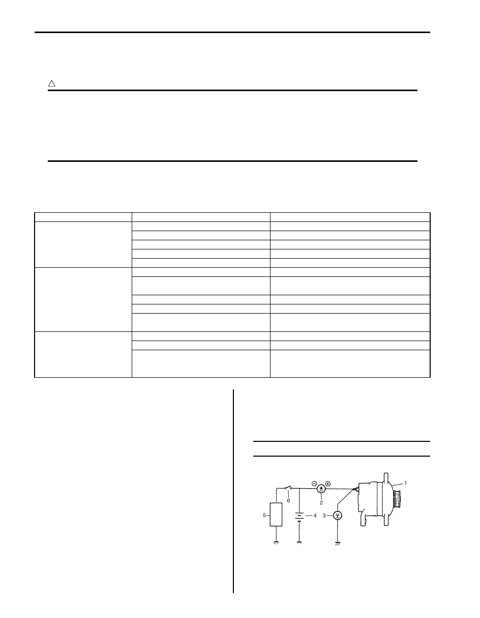
1. Generator with regulator assembly
4. Diode
7. Main switch
2. I.C. regulator
5. Field coil (rotor coil)
8. Battery
3. Stator coil
6. Charge indicator light
9. ECM
1J-4 Charging System:
Generator Symptom Diagnosis
S5JB0A1A04001
A charging circuit wiring diagram for generator connection is shown in “Generator Description”. To avoid damage,
always follow these precautions:
CAUTION
!
• Do not mistake polarities of “IG” terminal and “L” terminal.
• Do not create a short circuit between “IG” and “L” terminals. Always connect these terminals
through a lamp.
• Do not connect any load between “L” and “E” terminals.
• When connecting charger or booster battery to vehicle battery, refer to “Jump Starting in Case of
Trouble in charging system will show up as one or more of the following conditions:
1) Faulty charge indicator light operation.
2) An undercharged battery as evidenced by slow cranking or indicator clear with dark on light yellow dot.
3) An overcharged battery as evidenced by excessive spewing of electrolyte from vents.
Generator Test (Undercharged Battery Check)
S5JB0A1A04002
This condition, as evidenced by slow cranking or
indicator clear with dark or light yellow dot can be
caused by one or more of the following conditions even
though indicator lamp may be operating normal.
The following procedure also applies to cars with
voltmeter and ammeter.
1) Make sure that undercharged condition has not been
caused by accessories left on for extended period of
time.
2) Check drive belt for proper tension.
3) If battery defect is suspected, refer to “Battery
4) Inspect wiring for defects. Check all connections for
tightness and cleanliness, battery cable connections
at battery, starting motor, ignition ground cable and
no “C” terminal circuit at ground.
5) Connect switch (6), load (5), battery (4), voltmeter
(3) and ammeter (2) to generator (1) as shown in
figure.
Voltmeter: Set between generator “B” terminal
and ground.
Ammeter: Set between generator “B” terminal
and battery (+) terminal.
NOTE
Use fully charged battery.
6) Measure current and voltage.
Condition
Possible cause
Correction / Reference Item
Noisy generator
Loose drive belt
Adjust or replace drive belt.
Loose drive belt pulley
Check generator.
Loose mounting bolts
Check mounting condition.
Worn or dirty bearings
Check generator.
Defective diode or stator
Check generator.
Charge indicator light
does not light with
ignition ON and engine off
Fuse blown
Check fuse.
Indicator lamp (LED) faulty
Check BCM, combination meter and/or CAN
communication line.
Wiring connection loose
Tighten loose connection.
IC regulator faulty
Check generator.
Poor contact between brush and slip
ring
Repair or replace.
Charge indicator light
does not go out with
engine running
Battery requires frequent
recharging
Drive belt loose or worn
Adjust or replace drive belt.
IC regulator or generator faulty
Check charging system.
Wiring faulty
Repair wiring.
IYSQ011A0007-01

Charging System: 1J-5
No-Load Check
1) Run engine from idling up to 2000 rpm and read
meters.
NOTE
Turn off switches of all accessories (wiper,
heater etc.).
Specification for undercharged battery (No-load
check)
Current: 10 A
Voltage: 14.2 – 14.8 V (at 20
°C, 68 °F)
NOTE
Consideration should be taken that voltage
will differ somewhat with regulator case
temperature as shown in figure.
2) Using service wire, ground “C” terminal (1) of
generator.
3) Measure voltage between “B” terminal of generator
and body ground.
Voltage: 12.5 – 13.1 V (at 20
°C, 68 °F)
• If voltage is higher than standard value
If voltage is higher than standard value, check ground
of brushes.
If brushes are not grounded, replace IC regulator.
If voltage is lower than standard value, proceed to the
following check.
Load Check
1) Run engine at 2000 rpm and turn on head light and
heater motor.
2) Measure current and if it is less than 30 A repair or
replace generator.
Generator Test (Overcharged Battery Check)
S5JB0A1A04003
1) To determine battery condition, refer to “Battery
2) If obvious overcharge condition exists as evidenced
by excessive spewing of electrolyte, measure
generator “B” terminal voltage at engine 2000 rpm.
3) If measured voltage is higher than upper limit value,
proceed to disassemble generator.
4) Check ground of brushes. If brushes are not
grounded, replace IC regulator. Then check field coil
for grounds and shorts, referring to “Generator
Inspection”.
[A]: Regulated voltage (V)
[B]: Heat sink temperature (
°C)
16.0
15.5
14.3
15.2
14.8
14.2
13.3
14.6
15.0
14.5
14.0
13.5
13.0
-30
0
20
[A]
[B]
68
22
120 (˚C)
248 (˚F)
(V)
I5JB0A1A0006-02
I5JB0A1A0011-01
[A]: Regulated voltage (V)
[B]: Heat sink temperature (
°C)
16.0
15.5
14.3
15.2
14.8
14.2
13.3
14.6
15.0
14.5
14.0
13.5
13.0
-30
0
20
[A]
[B]
68
22
120 (˚C)
248 (˚F)
(V)
I5JB0A1A0006-02
Нет комментариевНе стесняйтесь поделиться с нами вашим ценным мнением.
Текст