Suzuki Grand Vitara JB416 / JB420. Manual — part 148
2B-22 Front Suspension:
14) Connect front fender lining clip (1) (if equipped with
head light auto leveling system).
15) Install stabilizer joints (1), and tighten nuts to
specified torque. When tightening, hold stud with
hexagon wrench.
Tightening torque
Stabilizer joint nut (a): 60 N·m (6.0 kgf-m, 43.5
lb-ft)
16) Install right side and left side front drive shaft
assembly referring to “Front Drive Shaft Assembly
Removal and Installation: Front in Section 3A”.
17) Install suspension control arm referring to
“Suspension Control Arm Removal and Installation”.
18) Install engine under cover.
19) Install wheels (right & left) and lower hoist.
20) After installation, be sure to fill specified power
steering fluid and bleed air referring to “P/S System
Air Bleeding Procedure in Section 6C”.
21) Adjust headlight auto leveling system, refer to
“Initialization of Auto Leveling Headlight System in
Section 9B”.
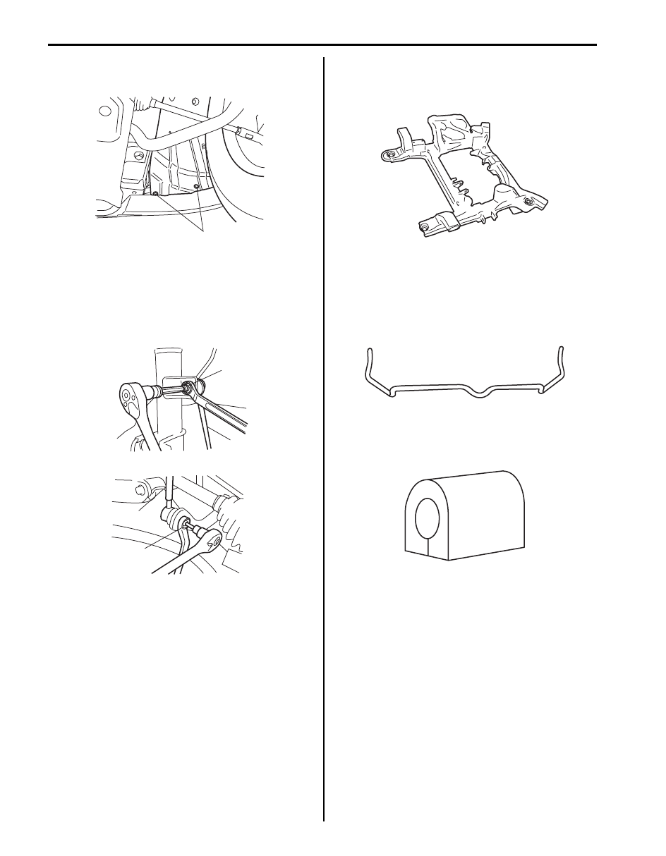
Front Suspension Frame Check
S5JB0A2206016
Inspect for cracks, deformation or damage.
If defective, replace.
Front Stabilizer Bar, Bushing and/or Joint
Check
S5JB0A2206017
Stabilizer Bar
Inspect for damage or deformation.
If defective, replace.
Stabilizer Bushing
Inspect for damage, wear or deterioration.
If defective, replace.
1
I5JB0A220042-01
(a)
1
1
(a)
I5JB0A220055-01
I5JB0A220056-01
I5JB0A220057-01
I5JB0A220058-01
Front Suspension: 2B-23
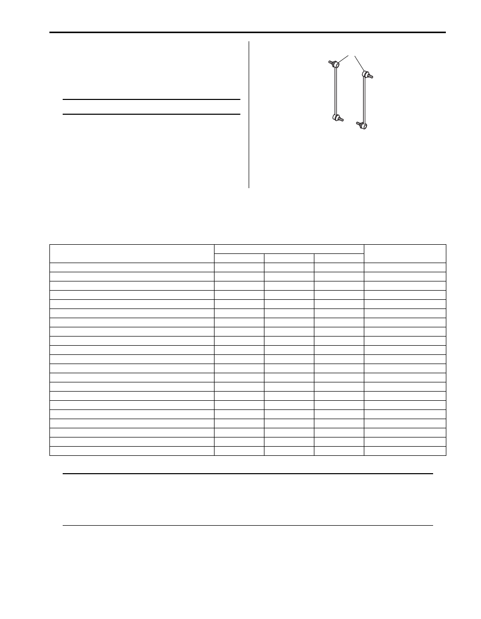
Stabilizer Joint
1) Check for smooth rotation.
2) Check damages of ball stud.
3) Check damages of dust cover.
NOTE
Stabilizer joint (1) cannot be disassembled.
If there is any damage to either parts, stabilizer joint
assembly must be replaced as a complete unit.
Front Suspension Fasteners Check
S5JB0A2206018
Check each bolt and nut fastening suspension parts for
tightness. Tighten loose one, if any, to specified torque,
referring to “Front Suspension Construction”.
Specifications
Tightening Torque Specifications
S5JB0A2207001
NOTE
The specified tightening torque is also described in the following.
“Front Suspension Construction”
“Front Strut Assembly Components”
“Front Wheel Hub Assembly and Steering Knuckle Components”
“Front Suspension Frame, Stabilizer Bar and/or Bushings Components”
Reference:
For the tightening torque of fastener not specified in this section, refer to “Fastener Information in Section 0A”.
1
I4RH01220007-01
Fastening part
Tightening torque
Note
N
⋅m
kgf-m
lb-ft
Tie-rod end lock nut
65
6.5
47.0
Strut bracket nut
135
13.5
98.0
Brake hose mounting bolt
25
2.5
18.0
Stabilizer joint nut
60
6.0
43.5
Front wheel speed sensor harness clamp bolt
10
1.0
7.5
Strut support nut
50
5.0
36.5
Wheel nut
100
10.0
72.5
Strut nut
90
9.0
65.0
Wheel hub housing bolt
50
5.0
36.5
Caliper carrier bolt
85
8.5
61.5
Drive shaft nut
220
22.0
159.5
Suspension arm ball joint nut
55
5.5
40.0
Front wheel speed sensor bolt
10
1.0
7.5
Tie-rod end nut
45
4.5
32.5
Suspension control arm ball joint nut
55
5.5
40.0
Suspension control arm nut
135
13.5
98.0
Stabilizer bar mounting bracket bolt
50
5.0
36.5
Suspension frame mounting bolt
135
13.5
98.0
Engine front body side mounting nut
55
5.5
40.0
Pipe bracket bolt
11
1.1
8.0
Union gear box bolt
35
3.5
25.5
2B-24 Front Suspension:
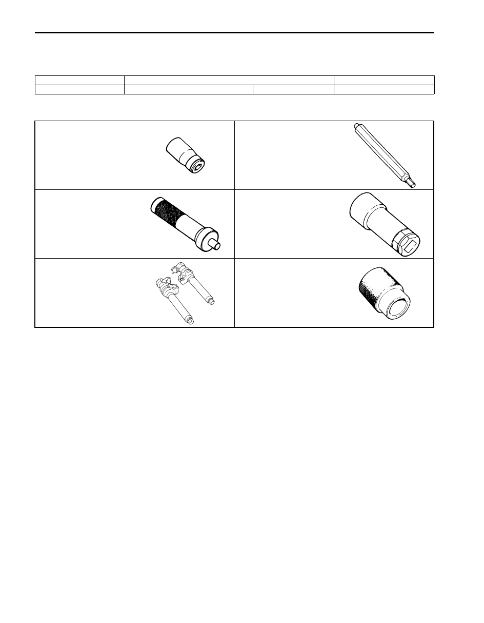
Special Tools and Equipment
Recommended Service Material
S5JB0A2208001
Special Tool
S5JB0A2208002
Material
SUZUKI recommended product or Specification
Note
Grease
SUZUKI Super Grease A
P/No.: 99000–25010
09900–00411
09900–00414
Hexagon bit socket
Hexagon bit (6 mm)
09913–75821
09941–56510
Bearing installer attachment
Socket wrench (19 mm)
09943–25010
09945–55410
Spring compressor
Bushing installer
Rear Suspension: 2C-1
Suspension
Rear Suspension
General Description
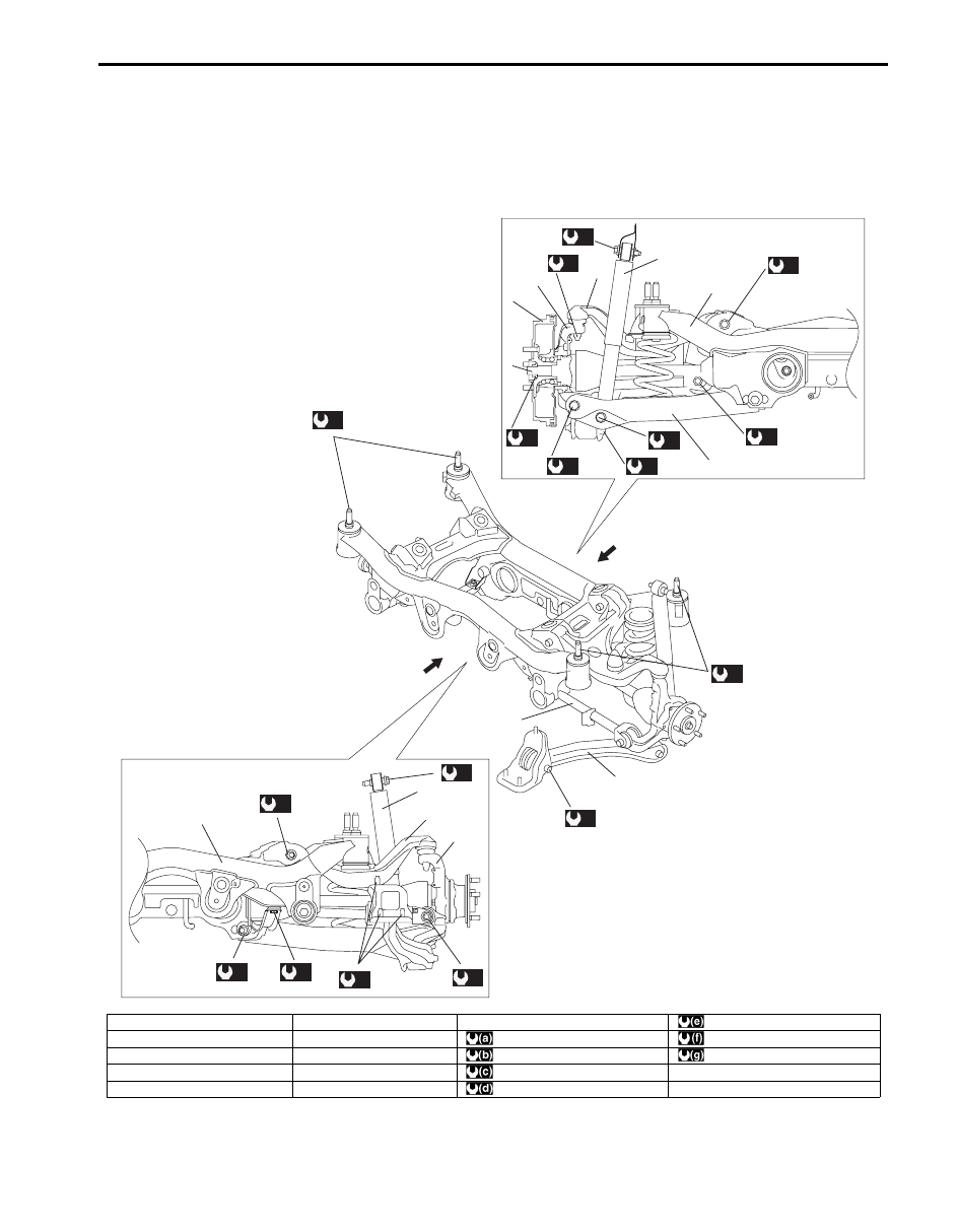
Rear Suspension Construction
S5JB0A2301001
4
5
(b)
(b)
A
B
A
3
8
1
2
(a)
(f)
(e)
(b)
(b)
(b)
B
6
7
8
9
(b)
(b)
(b)
(g)
(f)
(b)
(d)
(c)
1
2
3
(b)
I5JB0A230001-04
[A]: View A
4. Control rod
9. Lower Arm
: 50 N
⋅m (5.0 kgf-m, 36.5 lb-ft)
[B]: View B
5. Trailing rod
: 105 N
⋅m (10.5 kgf-m, 76.0 lb-ft)
: 60 N
⋅m (6.0 kgf-m, 43.5 lb-ft)
1. Rear shock absorber
6. Rear brake drum
: 135 N
⋅m (13.5 kgf-m, 98.0 lb-ft)
: 90 N
⋅m (9.0 kgf-m, 65.0 lb-ft)
2. Rear suspension knuckle
7. Rear drive shaft
: 55 N
⋅m (5.5 kgf-m, 40.0 lb-ft)
3. Rear suspension frame
8. Upper Arm
: 220 N
⋅m (22.0 kgf-m, 159.5 lb-ft)
Нет комментариевНе стесняйтесь поделиться с нами вашим ценным мнением.
Текст