Suzuki Grand Vitara JB416 / JB420. Manual — part 60

1A-189 Engine General Information and Diagnosis:
DTC P2101: Throttle Actuator Control Motor Circuit Range / Performance
S5JB0A1104077
Wiring Diagram
17 ABS warning lamp check
1) Connect connectors to all control modules
communicating by CAN.
2) Turn ignition switch ON.
Is ABS warning lamp light up?
Substitute a known-
good ABS hydraulic unit
/ control module
assembly and recheck.
Substitute a known-
good ECM and recheck.
Step
Action
Yes
No
E23
C37
3
4
18
19
5
6
7
10
11
17
20
47
46
49
50
51
21
22
52
16
25
9
24
14
29
55
57
54 53
59
60
58
2
26
27
28
15
30
56
48
32
31
34
35
36
37
40
42
39 38
44
45
43
41
33
1
12
13
23
8
3
4
18
19
5
6
7
10
11
17
20
47
46
49
50
51
21
22
52
16
25
9
24
14
29
55
57
54 53
59
60
58
2
26
27
28
15
30
56
48
32
31
34
35
36
37
40
42
39 38
44
45
43
41
33
1
12
13
23
8
12V
5V
BLU/BLK
BLU/BLK
BLK/RED
1
2
BLK/RED
BLK/RED
BLU
E23-1
E23-60
C37-15
C37-29
C37-48
BLK/ORN
C37-58
BLU/ORN
GRN
BLU/RED
BLU/YEL
BLU/RED
E23-16
E23-50
E23-17
C37-45
C37-44
1-1
1-2
1-3
3
4
5
8
6
7
10
9
E23-29
BLK/YEL
BLK/WHT
WHT/GRN
C37-30 BLK/ORN
BLK/YEL
BLK/YEL
BLK/YEL
BLU/BLK
BLU/BLK
WHT
BLK
RED
GRN
C37-53
C37-54
C37-40
C37-41
I5JB0A110069-01
1. Electric throttle body assembly
3. ECM
8. “IGN” fuse
1-1. Throttle actuator
4. Main relay
9. “IG COIL” fuse
1-2. Throttle position sensor (main)
5. Fuse box No.2
10. Ignition switch
1-3. Throttle position sensor (sub)
6. “THR MOT” fuse
2. Throttle actuator control relay
7. “FI” fuse
Engine General Information and Diagnosis: 1A-190
DTC Detecting Condition and Trouble Area
DTC Confirmation Procedure
1) With ignition switch turned OFF, connect scan tool.
2) Turn ON ignition switch and clear DTC using scan tool.
3) Keep the accelerator pedal at idle position for 2 seconds.
4) Keep the accelerator pedal at fully depressed position for 2 seconds.
5) Repeat Step 3) and 4) for 3 times.
6) Check DTC.
DTC Troubleshooting
NOTE
Before this trouble shooting is performed, read the precautions for DTC troubleshooting referring to
“Precautions For DTC Troubleshooting”.
DTC detecting condition
Trouble area
Monitor signal of throttle actuator output (duty output) is
inconsistent with throttle actuator control command.
(1 driving detection logic)
• Throttle actuator circuit
• Electric throttle body assembly
• ECM
Step
Action
Yes
No
1
Was “Engine and Emission Control System Check”
performed?
Go to Step 2.
Go to “Engine and
Emission Control
System Check”.
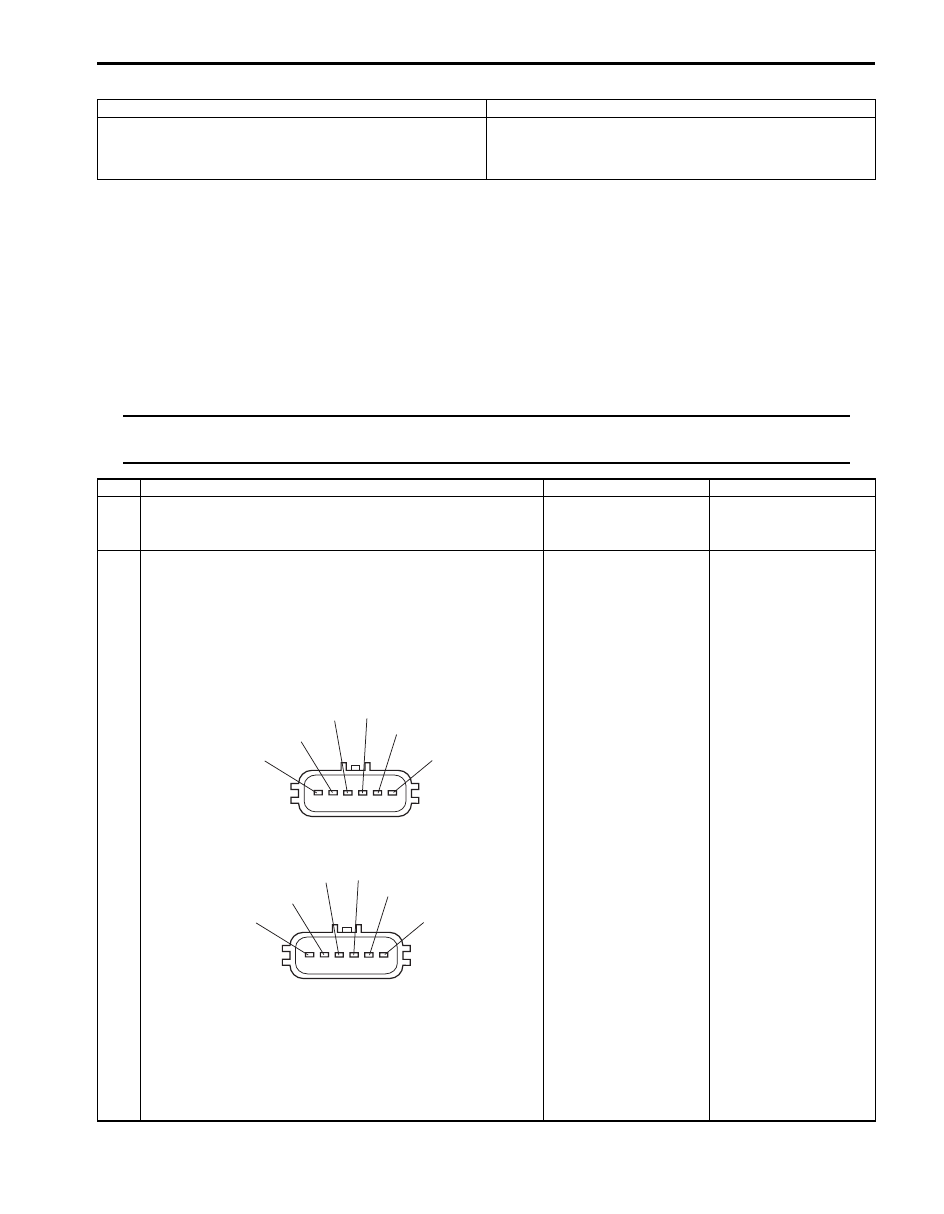
2
Throttle actuator circuit check
1) Disconnect connectors from electric throttle body
assembly and ECM with ignition switch turned OFF.
2) Check for proper connection of electric throttle body
assembly and ECM connectors at “BLU/YEL” wire,
“BLU/RED” wire, “C37-45” and “C37-44” terminals.
For J20 engine
For M16 engine
3) Turn ON ignition switch.
4) Measure voltage between “BLU/YEL” wire terminal of
electric throttle body assembly connector and engine
ground, between “BLU/RED” wire terminal of electric
throttle body assembly connector and engine ground.
Is voltage 0 V?
Go to Step 3.
“BLU/YEL” wire and/or
“BLU/RED” wire is
shorted to power circuit.
"BLK"
"WHT"
"RED"
"GRN"
"BLU/YEL"
"BLU/RED"
I5JB0A110042-01
"BLU/RED"
"BLU/YEL"
"GRN"
"RED"
"WHT"
"BLK"
I5JB0A110043-01

1A-191 Engine General Information and Diagnosis:
DTC P2102: Throttle Actuator Control Motor Circuit Low
S5JB0A1104078
Wiring Diagram
Refer to “DTC P2101: Throttle Actuator Control Motor Circuit Range / Performance”.
DTC Detecting Condition and Trouble Area
DTC Confirmation Procedure
1) With ignition switch turned OFF, connect scan tool.
2) Turn ON ignition switch and clear DTC using scan tool.
3) Start engine and run it for 1 min. or more.
4) Check DTC.
3
Throttle actuator circuit check
1) Turn OFF ignition switch.
2) Measure resistance between “BLU/YEL” wire terminal of
electric throttle body assembly connector and engine
ground, between “BLU/RED” wire terminal of electric
throttle body assembly connector and engine ground.
Is resistance infinity?
Go to Step 4.
“BLU/YEL” wire and/or
“BLU/RED” wire is
shorted to ground
circuit.
4
Throttle actuator circuit check
1) Check throttle actuator referring to “Throttle Actuator
(Motor) Check” under “Electric Throttle Body Assembly
On-Vehicle Inspection in Section 1C”.
Is check result satisfactory?
Substitute a known-
good ECM and recheck.
Replace electric throttle
body assembly.
Step
Action
Yes
No
DTC detecting condition
Trouble area
Power supply voltage of throttle actuator control circuit is
less than 5 V for specified time even if throttle actuator
control relay is turned on.
(1 driving detection logic)
• Throttle actuator control relay circuit
• Throttle actuator control relay
• ECM

Engine General Information and Diagnosis: 1A-192
DTC Troubleshooting
NOTE
Before this trouble shooting is performed, read the precautions for DTC troubleshooting referring to
“Precautions For DTC Troubleshooting”.
Step
Action
Yes
No
1
Was “Engine and Emission Control System Check”
performed?
Go to Step 2.
Go to “Engine and
Emission Control
System Check”
2
Throttle actuator control relay circuit check
1) Remove ECM from its bracket with ECM connectors
connected.
2) Check for proper connection of ECM connector at “E23-
50” and “E23-17” terminals.
3) Turn ON ignition switch.
4) Measure voltage between “E23-17” terminal of ECM
connector and engine ground.
Is voltage 10 – 14 V?
Intermittent trouble.
Check for intermittent
referring to “Intermittent
and Poor Connection
Inspection in Section
00”.
Go to Step 3.
3
Is “THR MOT” fuse in good condition?
Go to Step 4
Replace fuse and check
for short in circuits
connected to this fuse.
4
Throttle actuator control relay circuit check
1) Remove throttle actuator control relay from relay box
with ignition switch turned OFF.
2) Check for proper connection to throttle actuator control
relay at “BLU/BLK”, “BLU/RED”, “BLU/ORN” and “GRN”
wire terminals.
3) Measure voltage between engine ground and each
“BLU/BLK”, “BLU/RED” wire terminal with ignition switch
turned ON.
Is each voltage 10 – 14 V?
Go to Step 5
“BLU/BLK” wire and/or
“BLU/RED” wire is open
or high resistance.
5
Throttle actuator control relay circuit check
1) Disconnect connectors from ECM with ignition switch
turned OFF.
2) Measure resistance at following connector terminals.
• Between “BLU/ORN” wire terminal of throttle actuator
control relay connector and “E23-50” terminal of ECM
connector
• Between “GRN” wire terminal of throttle actuator
control relay connector and “E23-17” terminal of ECM
connector
Is each resistance below 3
Ω
?
Go to Step 6.
“BLU/ORN” wire and/or
“GRN” wire is open or
high resistance.
6
Throttle actuator control relay check
1) Check throttle actuator control relay referring to “Control
Relay Inspection in Section 1C”.
Is it in good condition?
Substitute a known-
good ECM and recheck.
Replace throttle
actuator control relay.
Нет комментариевНе стесняйтесь поделиться с нами вашим ценным мнением.
Текст