Suzuki Grand Vitara JB416 / JB420. Manual — part 233

5A-66 Automatic Transmission/Transaxle:
DTC P1777: TCM Lost Communication with ECM (Reception Error)
S5JB0A5104058
Wiring Diagram
Refer to “DTC P1774: CAN Communication Bus Off”.
DTC Detecting Condition and Trouble Area
DTC Confirmation Procedure
1) Connect scan tool to DLC with ignition switch turned OFF.
2) Turn ON ignition switch and clear DTC by using scan tool.
3) Start engine and run it for 1 min. or more.
4) Check DTC and pending DTC.
DTC Troubleshooting
NOTE
Upon completion of inspection and repair work, perform “DTC Confirmation Procedure: ” and confirm
that the trouble has been corrected.
DTC Detecting Condition
Trouble Area
Reception error of communication data for ECM is detected for
longer than specified time continuously.
(1 driving cycle detection logic)
• ECM
• ABS hydraulic unit / control module
• TCM
• CAN communication line circuit
Step
Action
Yes
No
1
Was “A/T System Check” performed?
Go to Step 2.
Go to “A/T System
Check”.
2
Control module connector check
1) Check connection of connectors of all control modules
communicating by means of CAN.
2) Recheck DTC in TCM referring to “DTC Check”.
Is there DTC P1777?
Go to Step 3.
Intermittent trouble.
Check for intermittent
referring to “Intermittent
and Poor Connection
Inspection in Section
00”.
3
DTC check in ABS hydraulic unit / control module
1) Check DTC in ABS hydraulic unit / control module.
Is there DTC U1100?
Go to Step 4.
Go to Step 5.
4
DTC check
1) Check DTC in ECM referring to “DTC Check in Section
1A”.
Is there DTC P1674?
Go to “DTC P1674:
CAN Communication
(Bus Off Error) in
Section 1A”.
Check ECM power and
ground circuit. If circuit
is OK, CAN
communication circuit
between ECM and ABS
hydraulic unit / control
module is open circuit.
5
CAN communication circuit check
1) Turn ignition switch to OFF position.
2) Disconnect connectors of all control modules
communicating by means of CAN.
3) Check CAN communication circuit between control
modules for open, short and high resistance.
Is each CAN communication circuit in good condition?
Check TCM power and
ground circuit. If circuit
is OK, substitute a
known-good TCM and
recheck.
Repair circuit.

Automatic Transmission/Transaxle: 5A-67
DTC P1778: TCM Lost Communication with BCM (Reception Error)
S5JB0A5104059
Wiring Diagram
Refer to “DTC P1774: CAN Communication Bus Off”.
DTC Detecting Condition and Trouble Area
DTC Confirmation Procedure
1) Connect scan tool to DLC with ignition switch turned OFF.
2) Turn ON ignition switch and clear DTC by using scan tool.
3) Start engine and run it for 1 min. or more.
4) Check DTC and pending DTC.
DTC Troubleshooting
NOTE
Upon completion of inspection and repair work, perform “DTC Confirmation Procedure: ”“DTC
Confirmation Procedure” and confirm that the trouble has been corrected.
DTC Detecting Condition
Trouble Area
Reception error of communication data for BCM is detected for
longer than specified time continuously.
(1 driving cycle detection logic)
• BCM
• TCM
• CAN communication line circuit
Step
Action
Yes
No
1
Was “A/T System Check” performed?
Go to Step 2.
Go to “A/T System
Check”.
2
Control module connector check
1) Check connection of connectors of all control modules
communicating by means of CAN.
2) Recheck DTC in TCM referring to “DTC Check”.
Is there DTC P1778?
Go to Step 3.
Intermittent trouble.
Check for intermittent
referring to “Intermittent
and Poor Connection
Inspection in Section
00”.
3
DTC check in BCM (bus off)
1) Check DTC in BCM referring to “DTC Check in Section
10B”.
Is there DTC U1073?
Go to “DTC U1073 (No.
1073): Control Module
Communication Bus Off
in Section 10B”.
Go to Step 4.
4
DTC check
1) Check DTC in ECM referring to “DTC Check in Section
Is there DTC P1678?
Check BCM power and
ground circuit. If circuit
is OK, substitute a
known-good BCM and
recheck.
Go to Step 5.
5
CAN communication circuit check
1) Turn ignition switch to OFF position.
2) Disconnect connectors of all control modules
communicating by means of CAN.
3) Check CAN communication circuit between control
modules for open, short and high resistance.
Is each CAN communication circuit in good condition?
Check TCM power and
ground circuit. If circuit
is OK, substitute a
known-good TCM and
recheck.
Repair circuit.
5A-68 Automatic Transmission/Transaxle:
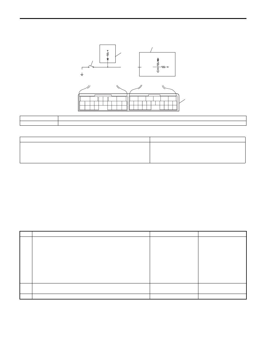
DTC P1874: 4L Switch Circuit Malfunction (Short)
S5JB0A5104047
Wiring Diagram
DTC Detecting Condition and Trouble Area
DTC Confirmation Procedure
1) Connect scan tool to DLC with ignition switch OFF.
2) Clear DTCs in TCM and ECM memories by using scan tool.
3) Start engine and transfer position switch to “4H” position.
4) Keep engine running at idle speed for 10 seconds or more with select lever “D” range.
5) Start vehicle and increase vehicle speed to about 60 km/h (37 mile/h) for 2 minutes.
6) Stop vehicle.
7) Check DTC, pending DTC and freeze frame data.
DTC Troubleshooting
12V
12V
PNK/WHT
BLK
E93-4
1
2
4
3
6
5
16 15 14 13 12 11
4 3
24 23
21
22
10 9
8
7
2
1
19
20
18 17
E92
17 16
26 25
15 14
6
5
3
4
2
13 12
23 22
24
11 10 9
21 20 19
8 7
18
1
E93
I5JB0A510026-01
1. 4L/N switch
3. 4WD control module
2. TCM
4. Terminal arrangement of TCM connector (viewed from harness side)
DTC Detecting Condition
Trouble Area
Actual transfer position is 4H although TCM detected 4L/N switch
is turned ON with vehicle speed between 29 km/h (18 mile/h) and
88 km/h (55 mile/h).
(1 driving cycle detection logic)
• 4L/N switch or its circuit.
• TCM
Step
Action
Yes
No
1
Vehicle speed signal check
1) Check DTC in ECM and ABS hydraulic unit / control
module referring to “DTC Check in Section 1A” or “DTC
Check in Section 4E”.
Is there DTC P P0500: Vehicle speed sensor (VSS)
malfunction in ECM and/or DTC C1021, C1022, C1025,
C1026, C1031, C1032, C1035 and/or C1036 in ABS
hydraulic unit / control module?
Go to applicable DTC
diag. flow.
Go to Step 2.
2
Was “A/T System Check” performed?
Go to Step 2.
Go to “A/T System
Check”.
3
Do you have SUZUKI scan tool?
Go to Step 4.
Go to Step 5.

Automatic Transmission/Transaxle: 5A-69
DTC P1875: 4L Switch Circuit Malfunction (Open)
S5JB0A5104048
Wiring Diagram
Refer to “DTC P1874: 4L Switch Circuit Malfunction (Short)”.
DTC Detecting Condition and Trouble Area
DTC Confirmation Procedure
1) Connect scan tool to DLC with ignition switch OFF.
2) Clear DTCs in TCM and ECM memories by using scan tool.
3) Start engine and transfer position switch to “4L” position.
4) Keep engine running at idle speed for 10 seconds or more with select lever “D” range.
5) Start vehicle and increase vehicle speed to about 50 km/h (31 mile/h) in “4L” position for 2 minutes.
6) Stop vehicle.
7) Check DTC, pending DTC and freeze-frame data.
4
4L switch and its circuit check
1) Connect SUZUKI scan tool to DLC with ignition switch
OFF.
2) Turn ignition switch ON.
3) Select “DATA LIST” mode on scan tool.
4) Check 4L/N switch signal (ON or OFF) on display when
turning transfer position switch to each position.
4L/N switch specifications (scan tool)
“4H” position: OFF
“4L” position: ON
Is OFF / ON displayed as described above?
Intermittent trouble or
faulty TCM. Check for
intermittent trouble
referring to “Intermittent
and Poor Connection
Inspection in Section
00”. If OK, substitute a
known-good TCM and
recheck.
Go to Step 6.
5
4L/N switch and its circuit check
1) Turn ignition switch ON.
2) Check terminal voltage “E93-4” of TCM connector
connected when turning transfer position switch to each
position.
4L/N switch specifications
“4H” position: 10 – 14 V
“4L” position: 0 – 1 V
Is voltage as specified?
Intermittent trouble or
faulty TCM. Check for
intermittent trouble
referring to “Intermittent
and Poor Connection
Inspection in Section
00”. If OK, substitute a
known-good TCM and
recheck.
Go to Step 6.
6
4L/N switch check
1) Check 4WD low switch for operation referring to
“Transfer Assembly Inspection: Motor-Shift Type
(Transfer with Shift Actuator) in Section 3C”.
Is check result satisfactory?
4L/N circuit is shorted to
ground. If wire and
connections are OK,
substitute a known-
good TCM and recheck.
Replace 4L/N switch.
Step
Action
Yes
No
DTC Detecting Condition
Trouble Area
Actual transfer position is 4L although TCM detected low switch is
turned OFF with vehicle speed between 29 km/h (18 mile/h) and
88 km/h (55 mile/h).
(1 driving cycle detection logic)
• 4L/N switch or its circuit.
• TCM
Нет комментариевНе стесняйтесь поделиться с нами вашим ценным мнением.
Текст