Suzuki Grand Vitara JB416 / JB420. Manual — part 232
5A-62 Automatic Transmission/Transaxle:
DTC P1702: Internal Control Module Memory Check Sum Error
S5JB0A5104044
DTC Detecting Condition and Trouble Area
NOTE
DTC P1702 can never be cleared once it has been set.
1) Ignition switch OFF.
2) Replace TCM.
3) Repeat “A/T System Check”.
DTC P1703: CAN Invalid Data - TCM
S5JB0A5104045
DTC Detecting Condition and Trouble Area
DTC Troubleshooting
4
Inspection solenoid valve
1) Inspection solenoid valve referring to “Solenoid Valves
Is check results satisfactory?
Intermittent trouble or
faulty TCM. Check for
intermittent trouble
referring to “Intermittent
and Poor Connection
Inspection in Section
00”. If OK, substitute a
known-good TCM and
recheck.
Replace defective
solenoid valve referring
to “Solenoid Valves
(Shift Solenoid-A, Shift
Solenoid-B, TCC
Pressure Control
Solenoid and Pressure
Control Solenoid
Removal and
Installation”.
Step
Action
Yes
No
DTC Detecting Condition
Trouble Area
An internal TCM fault is detected by TCM
(1 driving cycle detection logic)
TCM
DTC Detecting Condition
Trouble Area
When abnormality on the gear shift control signal from ECM is
detected by TCM, TCM sets DTC P1703.
(1 driving cycle detection logic)
• Engine control system
• TCM
• ECM
Step
Action
Yes
No
1
Was “A/T System Check” performed?
Go to Step 2.
Go to “A/T System
Check”.
2
DTC Check
Check DTC of ECM referring to “DTC Check in Section 1A”.
Is there any DTC(s)?
Go to applicable DTC
troubleshooting.
Substitute a known-
good TCM and recheck.
Automatic Transmission/Transaxle: 5A-63
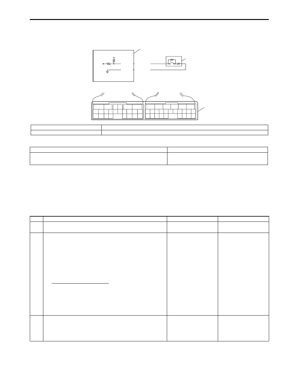
DTC P1723: Range Select Switch Malfunction
S5JB0A5104056
Wiring Diagram
DTC Detecting Condition and Trouble Area
DTC Confirmation Procedure
1) Connect scan tool to DLC with ignition switch OFF.
2) Clear DTCs in TCM and ECM memories by using scan tool.
3) Start engine and run it for 20 sec. or more.
4) Check DTC, pending DTC and freeze-frame data.
DTC Troubleshooting
5V
2
1
3
6
5
16 15 14 13 12 11
4 3
24 23
21
22
10 9
8
7
2
1
19
20
18 17
E92
17 16
26 25
15 14
6
5
3
4
2
13 12
23 22
24
11 10 9
21 20 19
8 7
18
1
E93
E92-20
E92-10
YEL/RED
YEL/BLK
I5JB0A510001-01
1. “3” position switch
3. Terminal arrangement of TCM connector (viewed from harness side)
2. TCM
DTC Detecting Condition
Trouble Area
“3” position switch signal is inputted out of specified value.
(1 driving cycle detection logic)
• “3” position switch or its circuit malfunction
• TCM
Step
Action
Yes
No
1
Was “A/T System Check” performed?
Go to Step 2.
Go to “A/T System
Check”.
2
Check “3” position switch circuit
1) Disconnect TCM connector with ignition switch OFF.
2) Check for proper connection to “3” position switch at
“E92-10” and “E92-20” terminals.
3) If OK, check resistance of switch circuit between
terminals “E92-10” and “E92-20” of disconnected
harness side TCM connector.
“3” position switch circuit
Shift selector lever to “P”, “N” or “D” range: 3.96 –
4.04 k
Ω
Shift selector lever to “R”, “3”, “2” or “L” range: 0.99
– 1.01 k
Ω
Is result as specified?
Intermittent trouble or
faulty TCM. Check for
intermittent trouble
referring to “Intermittent
and Poor Connection
Inspection in Section
00”. If OK, substitute a
known-good TCM and
recheck.
Go to Step 3.
3
Check “3” position switch
Check “3” position switch referring to ““3” Position Switch
Inspection”.
Is result as specified?
Replace “3” position
switch.
“3” position switch
circuit is malfunction.
5A-64 Automatic Transmission/Transaxle:
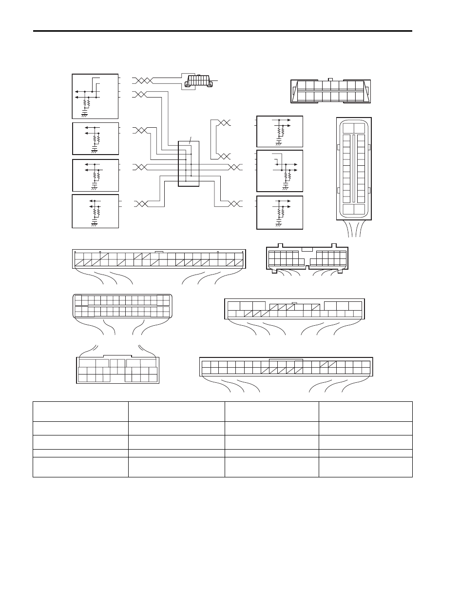
DTC P1774: CAN Communication Bus Off
S5JB0A5104057
Wiring Diagram
WHT
RED
WHT
RED
G44-18
G44-19
G44
[A]
[B]
[C]
[H]
[G]
1
2
3
4
5
6
7
8
9
10
11
14
15
16
36
34 33 32
30 29
24 23
37
18
19
20
G28-8
G28-10
WHT/BLU
WHT/BLU
WHT/RED
WHT/RED E23-4
E23-19
WHT
RED E03-12
E03-10
E03-6
E03-8
WHT
RED
E92-17
E92-7
WHT
RED
E91-22
E91-23
WHT
RED
WHT
RED
G31-1
G31-3
G31-2
G31-4
6
5
16 15 14 13 12 11
4 3
24 23
21
22
10 9
8
7
2
1
19
20
18 17
E92
2 1
E23
3
4
18
19
5
6
7
10
11
17
20
47 46
49
50
51
21
22
52
16
25
9
24
14
29
55
57
5453
59
60
58
26
27
28
15
30
56
48
32 31
34
35
36
37
40
42
3938
44
45
43
41
33
12
13
23
8
1
2
3
4
5
6
7
8
9
10
11
17
1615141312
2221201918
G28
[F]
G31
E91
1
2
3
4
7
8
9
10
11
14
15
16
36
34
35
24 23
21
22
28 27
25
26
37
39 38
40
18 17
13 12
19
20
1
2
3
10
11
12
16
17
18
15 14 13
19
20
21
25
26
5
6
[E]
[D]
E03
15
16
17
18
19
20
21
22
23
24
25
2
3
4
5
6
7
8
9
10
11
12
1
13
14
26
8 7 6 5 4 3 2 1
9
10
11
12
13
14
15
16
1
2
3
4
9
5
6
7
8
I5JB0A510002-01
[A]: Keyless start control module
connector (if equipped) (viewed
from harness side)
[F]: Combination meter connector
(viewed from harness side)
3. TCM
8. Combination meter
[B]: ECM connector (viewed from
harness side)
[G]: 4WD control module connector
(viewed from harness side)
4. Keyless start control module (if
equipped)
9. Junction connector
[C]: TCM connector (viewed from
harness side)
[H]: BCM connector (viewed from
harness side)
5. DLC
[D]: DLC (viewed from harness side)
1. BCM
6. ECM
[E]: ABS hydraulic unit / control
module connector (viewed from
harness side)
2. 4WD control module
7. ABS hydraulic unit / control
module

Automatic Transmission/Transaxle: 5A-65
DTC Detecting Condition and Trouble Area
DTC Confirmation Procedure
1) Connect scan tool to DLC with ignition switch turned OFF.
2) Turn ON ignition switch and clear DTC by using scan tool.
3) Start engine and run it for 1 min. or more.
4) Check DTC and pending DTC.
DTC Troubleshooting
NOTE
Upon completion of inspection and repair work, perform “DTC Confirmation Procedure: ” and confirm
that the trouble has been corrected.
DTC Detecting Condition
Trouble Area
Transmission error that is inconsistent between transmission data
and transmission monitor (CAN bus monitor) data is detected more
than 7 times continuously.
(1 driving cycle detection logic)
• ECM
• TCM
• Combination meter
• BCM
• ABS hydraulic unit / control module
• 4WD control module
• Keyless start control module (if equipped)
• CAN communication line circuit
Step
Action
Yes
No
1
Was “A/T System Check” performed?
Go to Step 2.
Go to “A/T System
Check”.
2
Control module connector check
1) Check connection of connectors of all control modules
communicating by means of CAN.
2) Recheck DTC in TCM referring to “DTC Check”.
Is there DTC P1774?
Go to Step 3.
Intermittent trouble.
Check for intermittent
referring to “Intermittent
and Poor Connection
Inspection in Section
00”.
3
CAN communication circuit check
1) Turn ignition switch to OFF position.
2) Disconnect connectors of all control modules
communicating by means of CAN.
3) Check CAN communication circuit between control
modules for open, short and high resistance.
Is each CAN communication circuit in good condition?
Go to Step 4.
Repair circuit.
4
DTC check
1) Turn ignition switch to OFF position.
2) Disconnect each connector.
ECM
ABS hydraulic unit / control module
BCM
4WD control module
Keyless start control module (if equipped)
Combination meter
3) Recheck DTC in TCM referring to “DTC Check”.
Is there DTC P1774?
Check TCM power and
ground circuit. If circuit
is OK, substitute a
known-good TCM and
recheck.
Check applicable
control module power
and ground circuit. If
circuit is OK, substitute
a known-good
applicable control
module and recheck.
Нет комментариевНе стесняйтесь поделиться с нами вашим ценным мнением.
Текст