Suzuki Grand Vitara JB416 / JB420. Manual — part 74
1A-245 Engine General Information and Diagnosis:
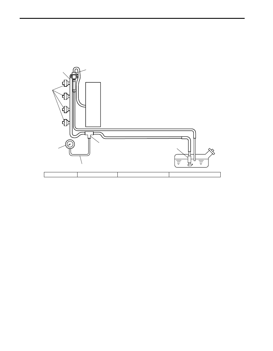
Fuel Pressure Check
S5JB0A1104067
System Diagram
Special tool
(A): 09912–58442
(B): 09912–58432
(C): 09912–58490
4
(C)
(B)
(A)
1
2
3
I2RH01110133-01
1. Injector
2. Delivery pipe
3. Fuel pressure regulator
4. Fuel filter and fuel pump
Engine General Information and Diagnosis: 1A-246
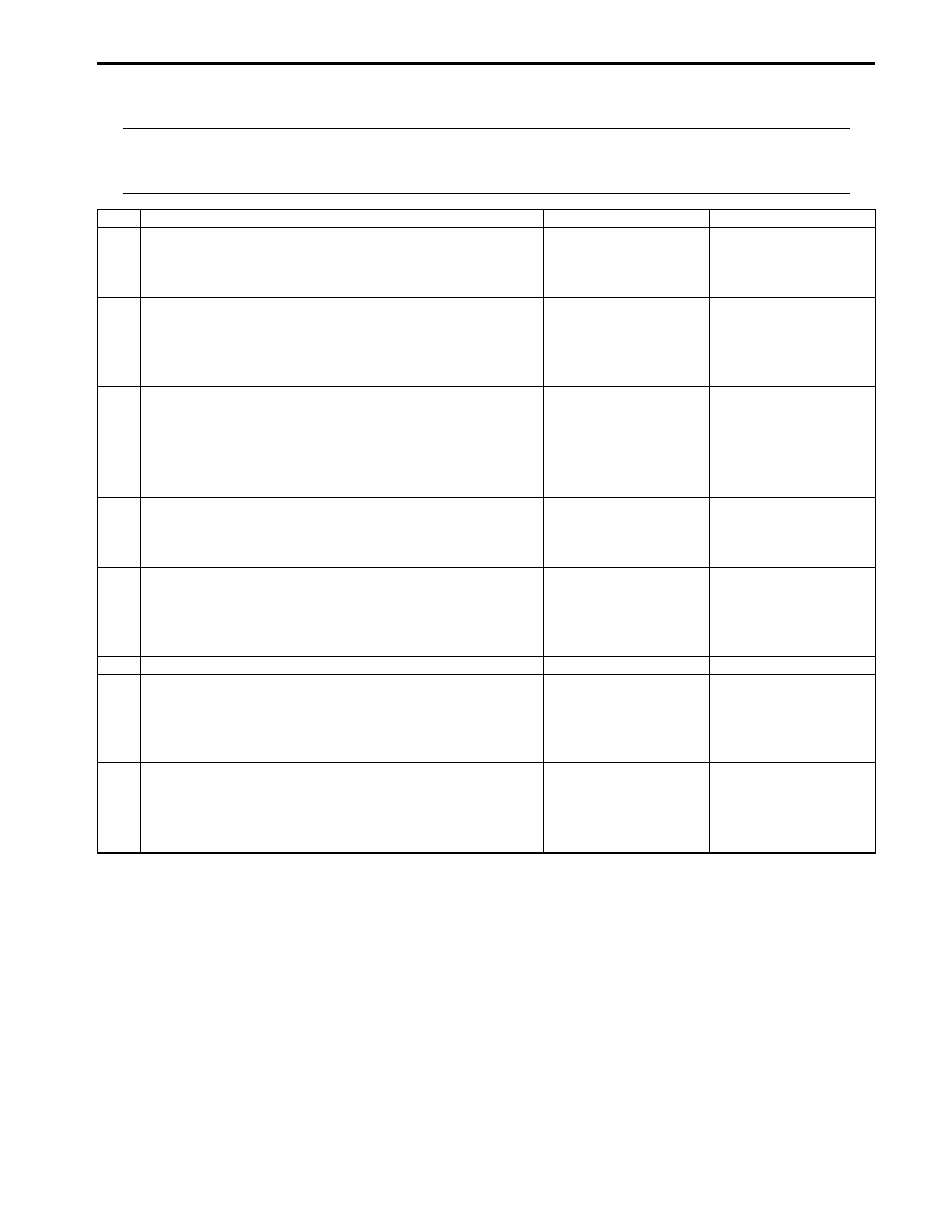
Troubleshooting
NOTE
Before using following flow, check to make sure that battery voltage is higher than 11 V. If battery
voltage is low, pressure becomes lower than specification even if fuel pump and line are in good
condition.
Step
Action
Yes
No
1
Fuel pump operating sound check
1) Remove fuel filler cap and then turn ON ignition switch.
Can you hear operating sound?
Go to Step 2.
Go to “Fuel Pump and
Its Circuit Check”.
2
Fuel pressure check
1) Check fuel pressure referring to “Fuel Pressure
Is check result satisfactory?
Go to Step 3.
Go to Step 6.
3
Fuel pressure check
1) Start engine and warm it up to normal operating
temperature.
2) Keep engine speed at 4000 rpm.
Does fuel pressure show about the same value as Step 2?
Go to Step 4.
Go to Step 8.
4
Fuel line check
1) Check fuel pipe, fuel hose and joint for fuel leakage.
Are they in good condition?
Go to Step 5.
Repair or replace
defective part.
5
Fuel line check
1) Check fuel pipe, fuel hose and joint for damage or
deform.
Are they in good condition?
Faulty fuel pressure
regulator.
Repair or replace
damaged or damaged
part.
6
Was fuel pressure higher than specification in Step 2?
Go to Step 7.
Go to Step 8.
7
Fuel line check
1) Check fuel pipe, fuel hose and joint for damage or
deform.
Are they in good condition?
Faulty fuel pressure
regulator.
Repair or replace
damaged or damaged
part.
8
Fuel line check
1) Check fuel pipe, fuel hose and joint for damage or
deform.
Are they in good condition?
Clogged fuel filter, faulty
fuel pump, faulty fuel
pressure regulator or
fuel leakage from hose
connection in fuel tank.
Repair or replace
defective part.

1A-247 Engine General Information and Diagnosis:
A/C System Circuits Check
S5JB0A1104069
Wiring Diagram
E23
C37
3
4
18
19
5
6
7
10
11
17
20
47
46
49
50
51
21
22
52
16
25
9
24
14
29
55
57
54 53
59
60
58
2
26
27
28
15
30
56
48
32
31
34
35
36
37
40
42
39 38
44
45
43
41
33
1
12
13
23
8
3
4
18
19
5
6
7
10
11
17
20
47
46
49
50
51
21
22
52
16
25
9
24
14
29
55
57
54 53
59
60
58
2
26
27
28
15
30
56
48
32
31
34
35
36
37
40
42
39 38
44
45
43
41
33
1
12
13
23
8
5V
RED/BLK
E23-46
E23-47
BLU/RED
BLU/YEL
BLU/BLK
E23-48
PPL/YEL
GRY/GRN
C37-24
C37-57
BLK
RED
YEL/GRN
RED/YEL
BLK
BLU
BLU
BLU/WHT
YEL/GRN
5V
WHT/BLU
WHT/RED
E23-4
E23-19
RED
WHT
WHT/BLU
WHT/RED
RED
WHT
5V
PNK/GRN
YEL/RED
WHT/BLK
BLK/RED
12V
PNK
*RED
GRY/RED
GRY/BLK
C37-14
C37-12
WHT/RED
E23-49
YEL/GRN
YEL/GRN
5V
1
2
4
9
11
12
15
16
5
8
14
13
7
10
3
6
I5JB0A110103-02
1. BCM
6. “IG2 SIG” fuse
11. Radiator cooling fan relay No.2
16. ECT sensor
2. ABS hydraulic unit / control
module assembly
7. “CPRSR” fuse
12. Radiator cooling fan relay No.3
*: For M16 engine
3. HVAC control module
8. Compressor relay
13. Radiator cooling fan No.1
4. ECM
9. Compressor
14. Radiator cooling fan No.2
5. Evaporator temperature sensor
10. Radiator cooling fan relay No.1
15. A/C refrigerant pressure sensor

Engine General Information and Diagnosis: 1A-248
Troubleshooting
NOTE
• Before performed troubleshooting, be sure to read the “Precautions of ECM Circuit Inspection”.
• When measuring circuit voltage, resistance and/or pulse signal at ECM connector, connect the
special tool to ECM and/or the ECM connectors referring to “Inspection of ECM and Its Circuits”.
• When A/C evaporator outlet air temp. is below 0
°C (32 °F) (for J20 engine) or 1.3 °C (34.3 °F) (for M16
engine), A/C remains OFF (“E23-49” terminal voltage becomes 10 – 14 V). This condition is not
abnormal.
Step
Action
Yes
No
1
Reception data check from BCM
1) Connect scan tool to DLC with ignition switch turned
OFF.
2) Turn ON ignition switch.
3) Check DTC for reception data from BCM.
Is there DTC P1678?
Go to applicable DTC
diag. flow.
Go to Step 2.
2
DTC check of HVAC control module
1) Check HVAC control module for DTC.
Is there DTC(s)?
Go to applicable DTC
diag. flow.
Go to Step 3.
3
A/C switch signal circuit check
1) Start engine and select “DATA LIST” mode on scan tool.
2) Check A/C switch signal under following conditions
respectively.
A/C switch signal
Engine running, A/C switch OFF: OFF
Engine running, A/C switch ON and blower speed
selector turned 1st position or more: ON
Is check result satisfactory?
Go to Step 4.
Check HVAC control
module and its circuit.
4
DTC check of ECT sensor circuit
1) Check ECM for DTC of ECT sensor circuit.
Is there DTC P0116, DTC P0117 or DTC P0118?
Go to applicable DTC
diag. flow.
Go to Step 5.
5
Radiator cooling fan control system check
Is radiator cooling fan started when A/C and blower speed
selector switch are turned ON with engine running?
Go to Step 11.
Go to Step 6.
6
Radiator cooling fan control circuit check
1) Check DTC with scan tool.
Is DTC P0480 displayed?
Go to “DTC P0480: Fan
1 (Radiator Cooling
Fan) Control Circuit”.
Go to Step 7.
7
Evaporator temperature sensor check
1) Check evaporator temperature sensor referring to “A/C
Evaporator Temperature Sensor Inspection in Section
7B”.
Is resistance within specification?
Go to Step 8.
Faulty evaporator
temperature sensor.
8
DTC check of A/C refrigerant pressure sensor circuit
1) Connect scan tool to DLC with ignition switch turned
OFF.
2) Turn ON ignition switch.
3) Check ECM for DTC of A/C refrigerant pressure sensor
circuit.
Is there DTC P0532 or DTC P0533?
Go to applicable DTC
diag. flow.
Go to Step 9.
Нет комментариевНе стесняйтесь поделиться с нами вашим ценным мнением.
Текст