Suzuki Grand Vitara JB416 / JB420. Manual — part 75

1A-249 Engine General Information and Diagnosis:
9
A/C refrigerant pressure sensor voltage check
1) Check A/C refrigerant pressure sensor voltage referring
to “Inspection of ECM and Its Circuits”.
Is voltage within specified value?
Go to Step 10.
Check amount of
refrigerant. If OK,
replace A/C refrigerant
pressure sensor.
10 Radiator cooling fan check
1) Check radiator cooling fan referring to “Radiator Cooling
Fan Motor On-Vehicle Inspection in Section 1F”.
Is check result satisfactory?
Radiator cooling fan
drive circuit malfunction.
If circuit is OK, go to
Step 7.
Replace radiator cooling
fan motor.
11 A/C compressor control system check
Is A/C compressor started when A/C and blower speed
selector switch are turned ON with engine running?
A/C system is in good
condition.
Go to Step 12.
12 A/C compressor relay circuit check
1) Measure voltage between “E23-49” wire terminal of
ECM connector and vehicle body ground under following
conditions respectively.
Voltage between “E23-49” terminal of ECM
connector and ground
While engine running and A/C switch turned OFF: 10
– 14 V
While engine running, A/C and blower speed
selector switch turned ON: 0 – 1 V
Is check result satisfactory?
Go to Step 13.
Go to Step 14.
13 A/C compressor relay check
1) Check A/C compressor relay referring to “A/C
Compressor Relay Inspection in Section 7B”.
Is it in good condition?
A/C compressor drive
circuit malfunction.
Replace A/C
compressor relay.
14 A/C compressor relay circuit check
1) Remove A/C compressor relay with ignition switch
turned OFF.
2) Turn ON ignition switch, measure voltage between “YEL/
GRN” wire terminal of A/C compressor relay connector
and vehicle body ground.
Is voltage 10 –14 V?
Go to Step 15.
“YEL/GRN” wire is open
circuit.
15 A/C compressor relay check
1) Check A/C compressor relay referring to “A/C
Compressor Relay Inspection in Section 7B”.
Is it in good condition?
“PNK” wire is open
circuit. If OK, substitute
a known-good ECM and
recheck.
Replace A/C
compressor relay.
Step
Action
Yes
No
Engine General Information and Diagnosis: 1A-250
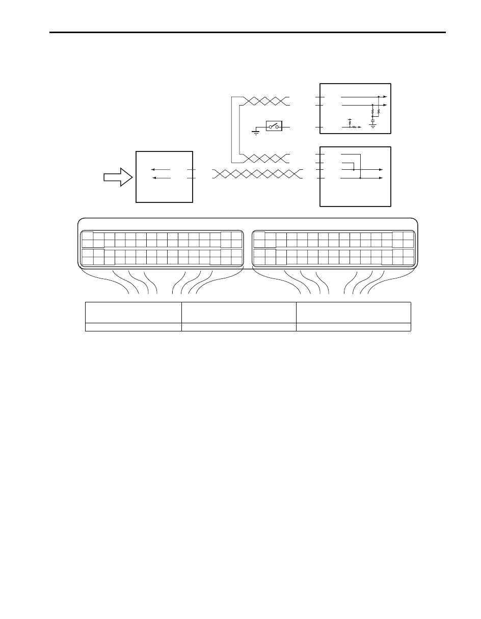
Electric Load Signal Circuit Check
S5JB0A1104070
Wiring Diagram
WHT/BLU
BLU/ORN
WHT/RED
E23
C37
3
4
18
19
5
6
7
10
11
17
20
47
46
49
50
51
21
22
52
16
25
9
24
14
29
55
57
54 53
59
60
58
2
26
27
28
15
30
56
48
32
31
34
35
36
37
40
42
39 38
44
45
43
41
33
1
12
13
23
8
3
4
18
19
5
6
7
10
11
17
20
47
46
49
50
51
21
22
52
16
25
9
24
14
29
55
57
54 53
59
60
58
2
26
27
28
15
30
56
48
32
31
34
35
36
37
40
42
39 38
44
45
43
41
33
1
12
13
23
8
E23-4
E23-19
1
RED
WHT
E03-12
E03-6
WHT/BLU
WHT/RED
E03-8
E03-10
RED
WHT
G31-3
G31-1
2
C37-7
3
5
12V
4
I5JB0A110104-02
1. ECM
3. ABS hydraulic unit / control module
assembly
5. Electric load signal (blower motor
signal, rear defogger signal, headlight
signal and A/C switch signal), etc.
2. BCM
4. PSP switch
1A-251 Engine General Information and Diagnosis:
Troubleshooting
NOTE
• Before performed troubleshooting, be sure to read the “Precautions of ECM Circuit Inspection”.
• When measuring circuit voltage, resistance and/or pulse signal at ECM connector, connect the
special tool to ECM and/or the ECM connectors referring to “Inspection of ECM and Its Circuits”.
Step
Action
Yes
No
1
DTC check
1) Connect scan tool to DLC with ignition switch turned
OFF.
2) Turn ON ignition switch and check DTC.
Is there DTC P1674 and/or P1678?
Go to applicable DTC
diag. flow.
Go to Step 2.
2
Electric load signal circuit check
1) Start engine and select “DATA LIST” mode on scan tool.
2) Check electric load signal under following conditions
respectively.
A/C switch signal
Engine running, A/C switch OFF: OFF
Engine running, A/C switch ON and blower speed
selector turned 1st position or more: ON
Blower fan signal
Engine running, blower speed selector OFF: OFF
Engine running, blower speed selector 5th position
or more: ON
PSP signal
Engine running, steering wheel to neutral position:
OFF
Engine running, turning steering wheel to the right
or left as far as it stops: ON
Electric load signal
Engine running, rear defogger switch or headlight
switch OFF: OFF
Engine running, rear defogger switch or headlight
switch ON: ON
Is check result satisfactory?
Electric load signal
circuit is in good
condition
Check defective signal
circuit.
Engine General Information and Diagnosis: 1A-252
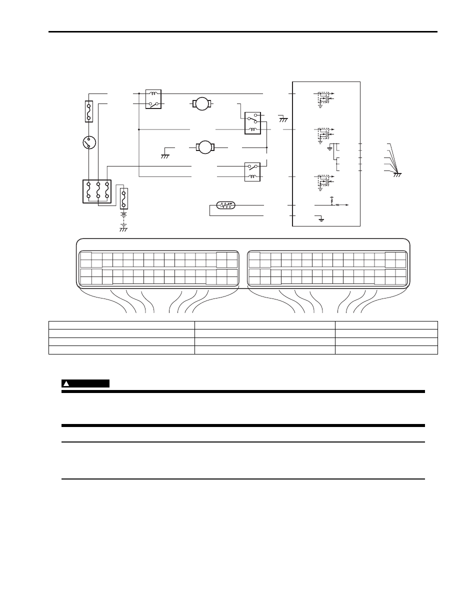
Radiator Cooling Fan Low Speed Control System Check
S5JB0A1104071
Wiring Diagram
Troubleshooting
WARNING
!
Keep hands, tools, and clothing away from engine cooling fan to help prevent personal injury. This fan
is electric and can come on whether or not the engine is running. The fan can start automatically in
response to the ECT sensor with the ignition switch at the “ON” position.
NOTE
• Before performed troubleshooting, be sure to read the “Precautions of ECM Circuit Inspection”.
• When measuring circuit voltage, resistance and/or pulse signal at ECM connector, connect the
special tool to ECM and/or the ECM connectors referring to “Inspection of ECM and Its Circuits”.
E23
C37
3
4
18
19
5
6
7
10
11
17
20
47
46
49
50
51
21
22
52
16
25
9
24
14
29
55
57
54 53
59
60
58
2
26
27
28
15
30
56
48
32
31
34
35
36
37
40
42
39 38
44
45
43
41
33
1
12
13
23
8
3
4
18
19
5
6
7
10
11
17
20
47
46
49
50
51
21
22
52
16
25
9
24
14
29
55
57
54 53
59
60
58
2
26
27
28
15
30
56
48
32
31
34
35
36
37
40
42
39 38
44
45
43
41
33
1
12
13
23
8
5V
RED/BLK
E23-46
E23-47
BLU/RED
BLU/YEL
BLU/BLK
E23-48
PPL/YEL
GRY/GRN
C37-24
C37-57
1
BLK
RED
YEL/GRN
C37-15
C37-29
C37-48
BLK/ORN
C37-58
C37-30 BLK/ORN
BLK/YEL
BLK/YEL
BLK/YEL
RED/YEL
BLK
BLU
BLU
YEL/GRN
BLU/WHT
YEL/GRN
8
4
5
9
2
10
3
6
7
I5JB0A110105-01
1. Fuse box No.1
5. Radiator cooling fan relay No. 3
9. ECT sensor
2. Ignition switch
6. Radiator cooling fan motor No.1
10. “IG2 SIG” fuse
3. Radiator cooling fan relay No. 1
7. Radiator cooling fan motor No.2
4. Radiator cooling fan relay No. 2
8. ECM
Нет комментариевНе стесняйтесь поделиться с нами вашим ценным мнением.
Текст