Suzuki Grand Vitara JB416 / JB420. Manual — part 171
3B-37 Differential: Rear
Specifications
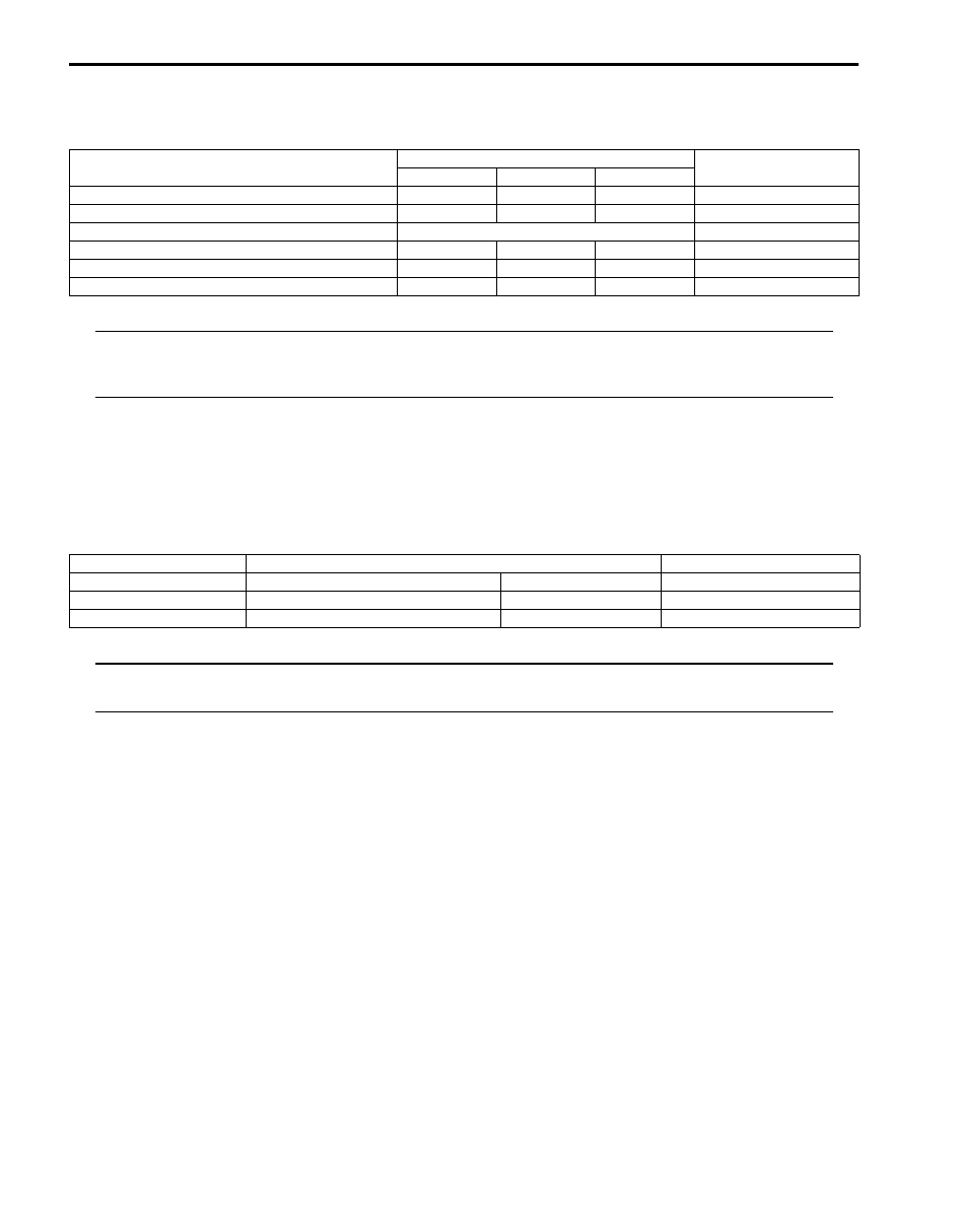
Tightening Torque Specifications
S5JB0A3227001
NOTE
The specified tightening torque is also described in the following.
“Rear Differential Unit Components: Rear”
“Rear Differential Components: Rear”
Reference:
For the tightening torque of fastener not specified in this section, refer to “Fastener Information in Section 0A”.
Special Tools and Equipment
Recommended Service Material
S5JB0A3228001
NOTE
Required service material is also described in the following.
“Rear Differential Components: Rear”
Fastening part
Tightening torque
Note
N
⋅m
kgf-m
lb-ft
Rear differential front mounting bolt
120
12.0
87.0
Rear differential rear mounting bolt
120
12.0
87.0
Bevel gear bolt
Tighten 40 N
⋅m (4.0 kgf-m, 29.5 lb-ft) + 50° )
Rear cover bolt No.1
50
5.0
17.0
Rear cover bolt No.2
60
6.0
43.5
Retainer bolt
50
5.0
36.5
Material
SUZUKI recommended product or Specification
Note
Grease
SUZUKI Super Grease A
P/No.: 99000–25010
Sealant
SUZUKI Bond No.1217G
P/No.: 99000–31260
Thread lock cement
Thread Lock Cement Super 1322
P/No.: 99000–32110
Differential: Rear 3B-38
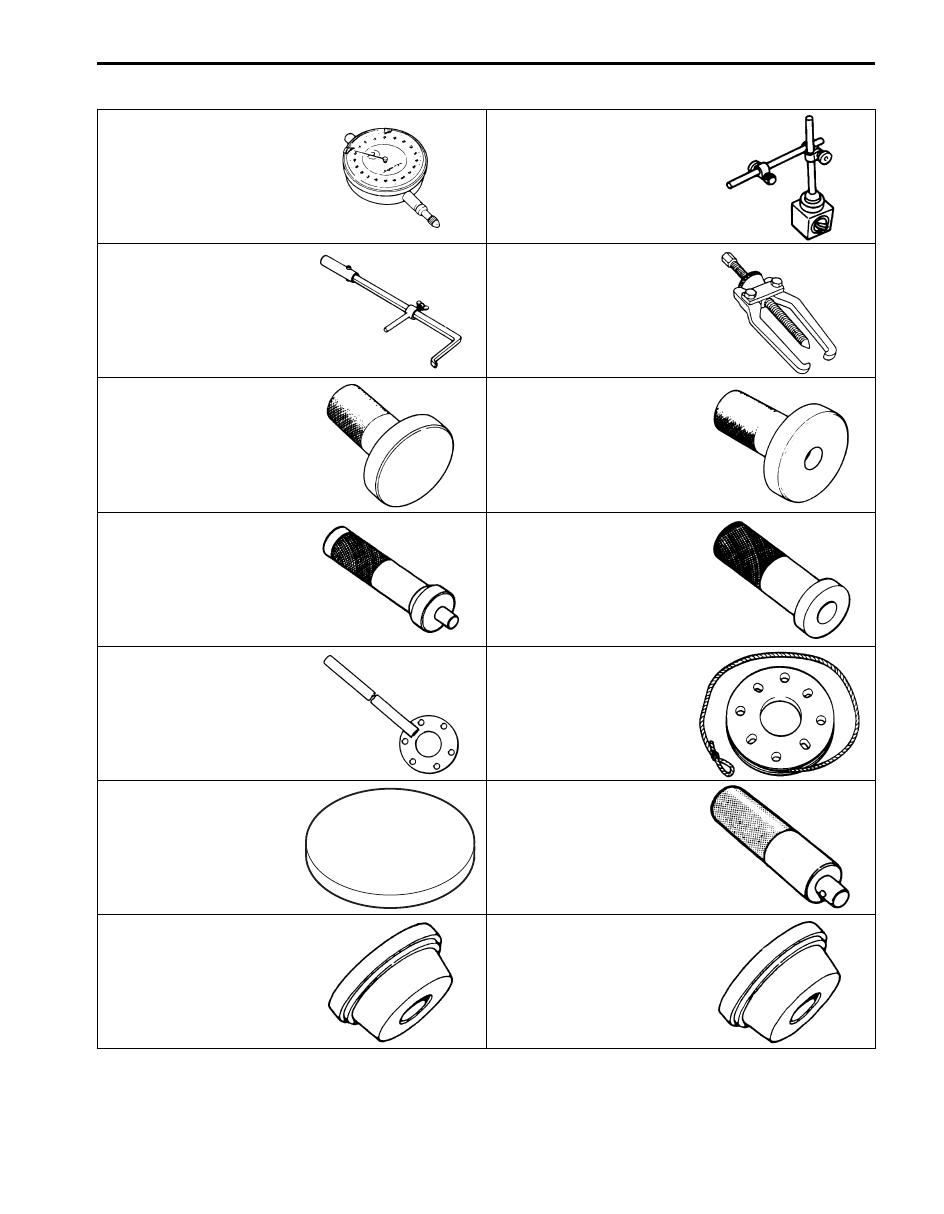
Special Tool
S5JB0A3228002
09900–20607
09900–20701
Dial gauge
Magnetic stand
09913–50121
09913–65135
Oil seal remover
Bearing puller
09913–75510
09913–75520
Bearing installer
Bearing installer
09913–75821
09913–85210
Bearing installer attachment
Bearing installer
09922–66021
09922–75222
Flange holder
Differential gear preload
adjuster
09922–76520
09924–74510
Bevel pinion gauge block
Bearing and oil seal handle
09924–84510–004
09924–84510–005
Bearing installer attachment
Bearing installer attachment
(D)

3B-39 Differential: Rear
09925–14520
09925–86010
Bearing and oil seal installer
(80 x 50 mm)
Bearing puller attachment
09925–88210
09926–78311
Bearing puller attachment
Differential bevel pinion
dummy
09926–78311–002
09926–78320
Pinion mounting dummy
Mounting dummy
09928–06510
09930–30104
Differential torque checking
tool
Sliding shaft
09940–53111
09941–64511
Differential side bearing
installer
Bearing and oil seal remover
(30 mm Min.)
09942–15511
09943–17912
Sliding hammer
Wheel hub remover
09951–16070
09951–16090
Shim adjuster attachment
Oil seal installer
09951–18210
09951–46010
Oil seal remover & installer
No. 2
Drive shaft oil seal installer
Transfer: Motor-Shift Type (Transfer with Shift Actuator) 3C-1
Driveline / Axle
Transfer
Motor-Shift Type (Transfer with Shift Actuator)
Precautions
Transfer Warning
S5JB0A3310002
WARNING
!
This transfer has a center differential.
When testing with 2-wheel chassis
dynamometer or speedometer tester (which
tester roller is driven by vehicle wheels), be
sure to make the vehicle as rear wheel drive
or as front wheel drive temporarily as
follows.
Otherwise, front wheels drive rear wheels or
vise-versa and personal injury may result.
1) Remove front propeller shaft or rear propeller shaft
referring to “Propeller Shaft Removal and Installation
in Section 3D”.
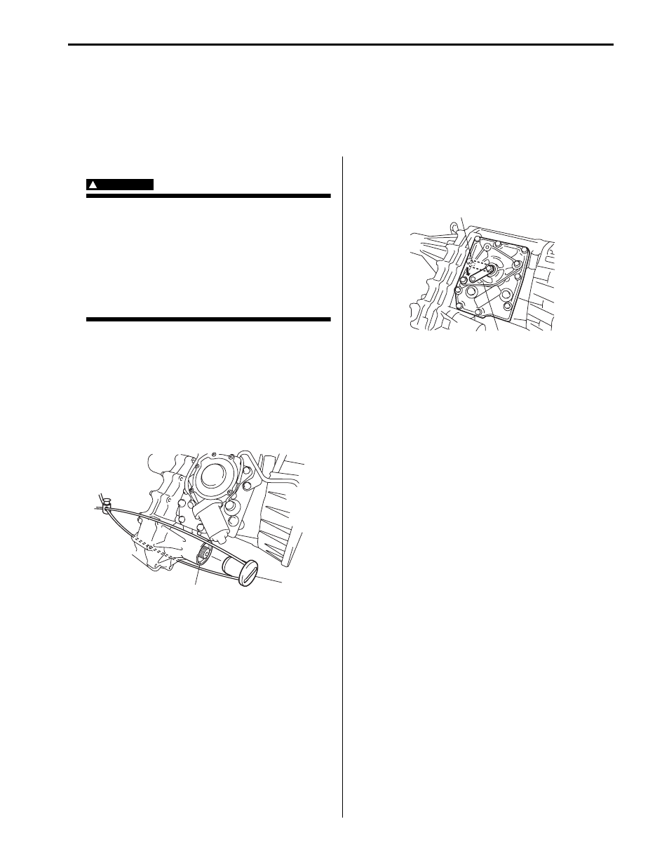
2) Install special tool (cap) to flange yoke cover hole
(front or rear) of transfer (1) and fix it to transfer or
hook with string to prevent oil leakage from transfer.
Special tool
(A): 09928–36510
3) Pour specified oil into transfer up to lever plug hole if
front propeller shaft is removed.
4) Shift transfer to 4H-lock position as follows.
• M16 engine model:
Remove lever bolt (1) on transfer, push down
lever to 4H-lock position (2) and fix lever with bolt.
• J20 engine model:
Shift transfer to 4H-lock position by turning
transfer switch.
Precautions in Diagnosing Trouble
S5JB0A3310001
• Do not disconnect the following parts before
confirming diagnostic information (DTC, etc.) stored in
4WD control module memory. These actions will
erase memorized information in 4WD control module
memory.
– Disconnection of coupler from 4WD control module
– Disconnection of battery cable from battery
– Disconnection of ground wire harness of 4WD
control module
– Disconnect main fuse from fuse box
• Diagnostic information stored in 4WD control module
memory can be cleared as well as checked by using
SUZUKI scan tool. Before using scan tool, read its
Operator’s (Instruction) Manual carefully to have good
understanding as to what functions are available and
how to use it.
• Be sure to read “Precautions for Electrical Circuit
Service:” before inspection and observe what is
written there.
(A)
1
I5JB0A331107-03
2
1
I5JB0A331108-01
Нет комментариевНе стесняйтесь поделиться с нами вашим ценным мнением.
Текст