Suzuki Grand Vitara JB416 / JB420. Manual — part 172

3C-2 Transfer: Motor-Shift Type (Transfer with Shift Actuator)
General Description
Transfer Description
S5JB0A3311010
The aluminum transfer case directly connected to the back of the transmission contains input gear, counter gear, rear
output shaft, front output shaft, center differential, drive chain and their accompanying gears, hubs, sleeves, fork, etc.
The center differential is installed in the transfer. With the torque induction type LSD used in the center differential, the
effect of LSD works when a rotation difference between front and rear wheels is occurring.
The transfer has such a selective mechanism as to enable the shift actuator to make selection of high speed (direct
connection with transmission output: main shaft), low speed (speed reduction by input gear, counter gear and low
gear) or neutral by way of the reduction shift sleeve located between the input gear and low gear, and selection of
center differential lock or not by way of the differential lock clutch sleeve located at the center of the rear output shaft.
The case has an oil pump to provide proper lubrication.
4WD Control System Description
S5JB0A3311002
Transfer Shift Control
The 4WD control module controls the transfer shift actuator based on the signal from the transfer switch so that the
transfer is shifted to the selected position (4H, 4H-lock, N or 4L-lock). (Shifting to the N position requires that the
switch to “” position (1) keep it there for about 10 seconds then turn it to “N” position.)
The transfer actuator consists of the actuator motor and the actuator motor position switch. The 4WD control module
detects the position of the actuator motor using the position switch and controls the actuator motor running / stopping
operation.
Also, the 4L/N switch and center differential lock switch that detect the each position of the High / Low shift fork and
the differential lock shift fork are installed the transfer assembly. The 4WD control module detects the transfer actual
shift position (4H, 4H-lock, N or 4L-lock) by the signals from the 4L/N switch and center differential lock switch as
follows.
Relationship of transfer shift position and switches
When the transfer shift actuator motor position detected by motor position switch and transfer actual shift position
detected by the above-mentioned switches match, the 4WD control module judges that the transfer shifting is
complete.
Retry Control
When 4WD control module cannot judge the shifting to the target position, it commands to retry the shifting up to 3
times. If retry shifting is not possible, previous shift position is restored and notify failure of the shifting with the
indicator and buzzer.
Indicator And Buzzer Operation
The 4WD control module output operation signal of the differential lock indicator, 4L indicator, N indicator and the
buzzer to BCM. Indicators and buzzer as follows in order to inform what state the transfer control system is.
Switch
Transfer shift position
4H
4H-lock
N
4L-lock
4L/N switch
OFF
OFF
ON
ON
Center differential lock switch
ON
OFF
ON
OFF
1
I5JB0A332002-01

Transfer: Motor-Shift Type (Transfer with Shift Actuator) 3C-3
Operation
Condition
Indicator
Buzzer
Differential
lock
indicator
OFF
—
• Ignition switch is OFF.
• Transfer is at 4H/N position.
ON
—
• Within 2 seconds after ignition switch is turn ON (checking
indicator operation).
• Transfer is at 4H-lock/4L-lock position.
Flashes at 0.25
seconds for 3
times, at intervals
of 20 seconds.
Sounds at 1
second at
intervals of 20
seconds.
• The transfer shift position is different for transfer switch.
Flashes at
intervals of 0.25
seconds
continuously
—
• 4WD control module detects DTC of 4WD control system.
Flashes at
intervals of 0.5
seconds
continuously
—
• Transfer is shifting from 4H to 4H-lock.
• Transfer is shifting from 4H-lock to 4H.
• Transfer could not complete shifting to 4H-lock.
4L indicator
OFF
—
• Ignition switch is OFF.
• Transfer is at 4H-lock/N position.
ON
—
• Within 2 seconds after ignition switch is turn ON (checking
indicator operation).
• Transfer is at 4L-lock position.
Flashes at 0.25
seconds for 3
times, at intervals
of 20 seconds.
Sounds at 1
second at
intervals of 20
seconds.
• The transfer shift position is different for transfer switch.
Flashes at
intervals of 0.25
seconds
continuously
—
• 4WD control module detects DTC of 4WD control system.
Flashes at
intervals of 0.5
seconds
continuously
—
• Transfer is shifting from 4H-lock to 4L-lock.
• Transfer is shifting from 4L-lock to 4H-lock.
• Transfer could not complete shifting to 4L-lock.
N indicator
OFF
—
• Ignition switch is OFF.
• Transfer is at 4H/4H-lock/4L-lock position.
ON
—
• Within 2 seconds after ignition switch is turn ON (checking
indicator operation).
• Transfer is at N position.
Flashes at 0.25
seconds for 3
times, at intervals
of 20 seconds.
Sounds at 1
second at
intervals of 20
seconds.
• The transfer shift position is different for transfer switch.
Flashes at
intervals of 0.2
seconds
continuously
—
• 4WD control module detects DTC of 4WD control system.
Flashes at 0.5
seconds
continuously
—
• Transfer could not complete shifting to N.
—
—
Sounds at 0.2
seconds for 2
times, at intervals
of 3 seconds.
• Transfer is at N position.

3C-4 Transfer: Motor-Shift Type (Transfer with Shift Actuator)
Function of 4WD Control System Component
S5JB0A3311003
4WD Control System Operation
S5JB0A3311005
Instead of the transfer shift lever assembly, the transfer position (4H, 4H-lock, N and 4L-lock) is shifted automatically
by operating the transfer switch.
The 4WD control module operates the transfer shift actuator according to the transfer switch operation.
4H (4WD High) Position
The driving force from the transmission is transmitted to the transfer input gear. As the center LSD case and transfer
input gear are engaged via the reduction shift sleeve at this time, the driving force transmitted from the transfer input
gear to the rear output shaft rotates them at the same speed.
Also, driving force from the center LSD is transmitted to the front drive shaft through front drive sprocket. Then, the
front drive sprocket rotates the front output shaft via the drive chain.
Part Name
Function
4L/N switch
Detects transfer shift position combining center differential lock
switch.
Center differential lock switch
Detects transfer shift position combining 4L/N switch.
Transfer switch
Shifts transfer shift position.
N indicator
Indicates transfer is at N position or not.
4L indicator
Indicates transfer is at 4L-lock position or not.
Differential lock indicator
Indicates transfer is at 4H-lock, 4L-lock or not.
Transmission range sensor (N position) (for A/T
model)
Detects A/T is at N range or not.
CPP switch
Detects clutch pedal is depressed or not.
Buzzer incorporated into BCM
• Indicates transfer is at “N” position.
• Warns of prohibited shift operation.
4WD control module
• Controls transfer shifting.
• Diagnoses 4WD control system components.
• Output operation signal of indicators and buzzer to BCM.
Transfer shift actuator
• Consists of transfer shift actuator motor and transfer shift
actuator motor position switch.
• Shifts transfer shift position operating High / Low shift fork and
differential lock shift fork via cams.
• Detects transfer shift actuator motor position.
Diagnosis connector
Indicates DTC on indicators when grounding its diagnosis
terminal.
Transfer: Motor-Shift Type (Transfer with Shift Actuator) 3C-5
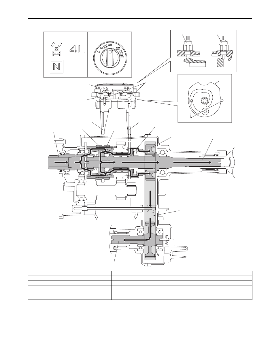
4H-lock (4WD High Center Differential Lock) Position
When 4H-lock position is selected from 4H position by turning the transfer switch, the transfer shift control actuator
motor runs and shift cam rotates in the arrow direction “A”. The shift cam shifts the differential lock shift fork in the
arrow direction “B”, and the differential lock clutch sleeve also moves in the arrow direction “B”.
[A]
[B]
1
2
5
4
4
3
5
9
8
6
7
11
12
13
14
15
10
I5JB0A332003-02
[A]: Transfer position indicator
5. Shift cam
11. Front drive shaft
[B]: Transfer switch
6. High / Low shift fork
12. Front drive sprocket
1. 4L/N switch
7. Differential lock shift fork
13. Rear output shaft
2. Center differential lock switch
8. Input gear
14. Drive chain
3. Transfer actuator
9. Reduction shift sleeve
15. Front output shaft
4. Shift fork pin
10. Center LSD case
Нет комментариевНе стесняйтесь поделиться с нами вашим ценным мнением.
Текст