Suzuki Grand Vitara JB416 / JB420. Manual — part 153
2C-18 Rear Suspension:
Installation
1) Install upper arm.
a) Install upper arm (2) to rear suspension frame.
b) Insert upper arm bolt (1) from the upper arm
inside.
c) Tighten upper arm mount nuts (3) temporarily by
hand.
CAUTION
!
If reuse upper arm mount nut, apply engine
oil to thread and bearing.
2) Tighten wheel sensor bolts (1) to specified torque.
Tightening torque
Wheel sensor bolt (a): 11 N·m (1.1 kgf-m, 8.0 lb-
ft)
3) Install rear suspension knuckle refer to “Rear
Suspension knuckle Removal and Installation”.
4) Install trailing rod refer to “Trailing Rod Removal and
5) Install control rod refer to “Control Rod Removal and
6) Install lower arm refer to “Lower Arm Removal and
7) Install rear wheels and lower hoist.
8) Tighten wheel nuts to specified torque.
Tightening torque
Wheel nut: 100 N·m (10.0 kgf-m, 72.5 lb-ft)
9) Tighten each bolts and nuts to specified torque with
vehicle weight on suspension.
CAUTION
!
• It is the most desirable to have vehicle off
hoist and in non-loaded condition when
tightening them.
• Tighten lower arm washer and control rod
washer with match marks aligned.
Tightening torque
Upper arm mount nut: 135 N·m (13.5 kgf-m, 98.0
lb-ft)
Shock absorber upper bolt: 60 N·m (6.0 kgf-m,
43.5 lb-ft)
Shock absorber lower bolt: 90 N·m (9.0 kgf-m,
65.0 lb-ft)
Lower arm outer bolt: 135 N·m (13.5 kgf-m, 98.0
lb-ft)
Lower arm mount nut: 135 N·m (13.5 kgf-m, 98.0
lb-ft)
Control rod outer bolt: 135 N·m (13.5 kgf-m, 98.0
lb-ft)
Control rod mount nut: 135 N·m (13.5 kgf-m,
98.0 lb-ft)
Trailing rod rear bolt: 135 N·m (13.5 kgf-m, 98.0
lb-ft)
Trailing rod mount nut: 135 N·m (13.5 kgf-m,
98.0 lb-ft)
10) Check rear toe and camber adjust it as necessary.
For check and adjustment procedures, refer to “Rear
Wheel Alignment Inspection and Adjustment”.
11) Adjust headlight auto leveling system, refer to
“Initialization of Auto Leveling Headlight System in
Section 9B”.
1
2
3
3
I5JB0A230041-01
1,(a)
I5JB0A230042-01
Rear Suspension: 2C-19
Upper Arm / Bushing Disassembly and
Assembly
S5JB0A2306035
Disassembly
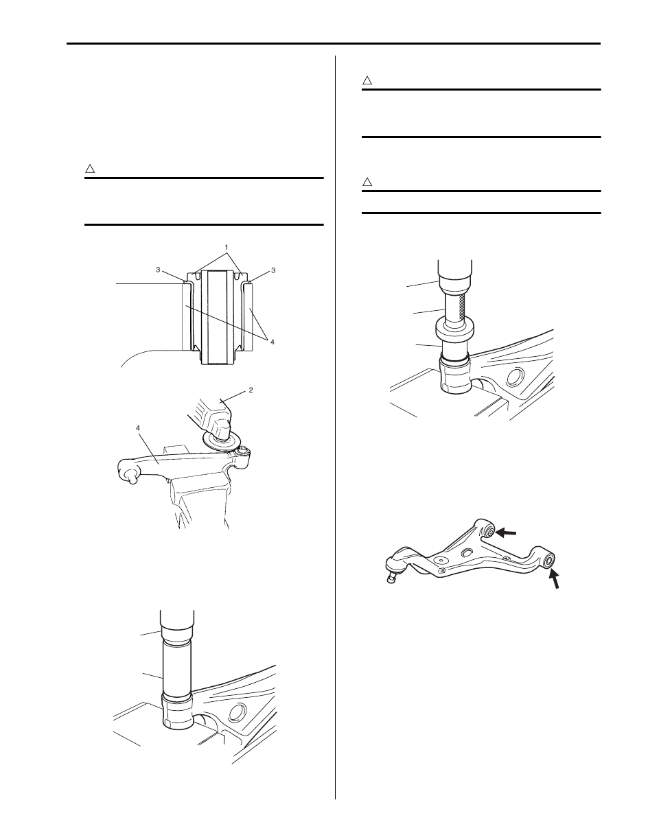
1) Cut rubber (1) of flange of upper arm bushing.
2) Using grinder (2), grind off flange (3) of upper arm
bushing.
CAUTION
!
Be careful not to damage upper arm (4) when
grinding flange (3) of upper arm bushing with
grinder.
3) Push out upper arm bushing by using hydraulic
press (1) and special tool.
Special tool
(A): 09913–68711
Assembly
CAUTION
!
Apply grease (included in the repair kit) to
ball joint and inside of ball stud boot when
the ball stud boot is replaced.
1) Press-fit upper arm bushing (2) by using press (1)
and special tool.
CAUTION
!
Be sure to use new bushing.
Special tool
(A): 09913–75510
Upper Arm Check
S5JB0A2306036
• Inspect for cracks, deformation or damage.
• Inspect bushing for wear and breakage.
If any faulty condition is found, replace.
I5JB0A230043-01
1
(A)
I5JB0A230044-02
1
(A)
2
I5JB0A230084-01
I5JB0A230045-01
2C-20 Rear Suspension:
Rear Suspension Frame Components
S5JB0A2306014
F
3
2
(a)
(b)
(b)
(b)
1
3
4
5
4
5
6
6
7
8
8
2
I6JB01230009-01
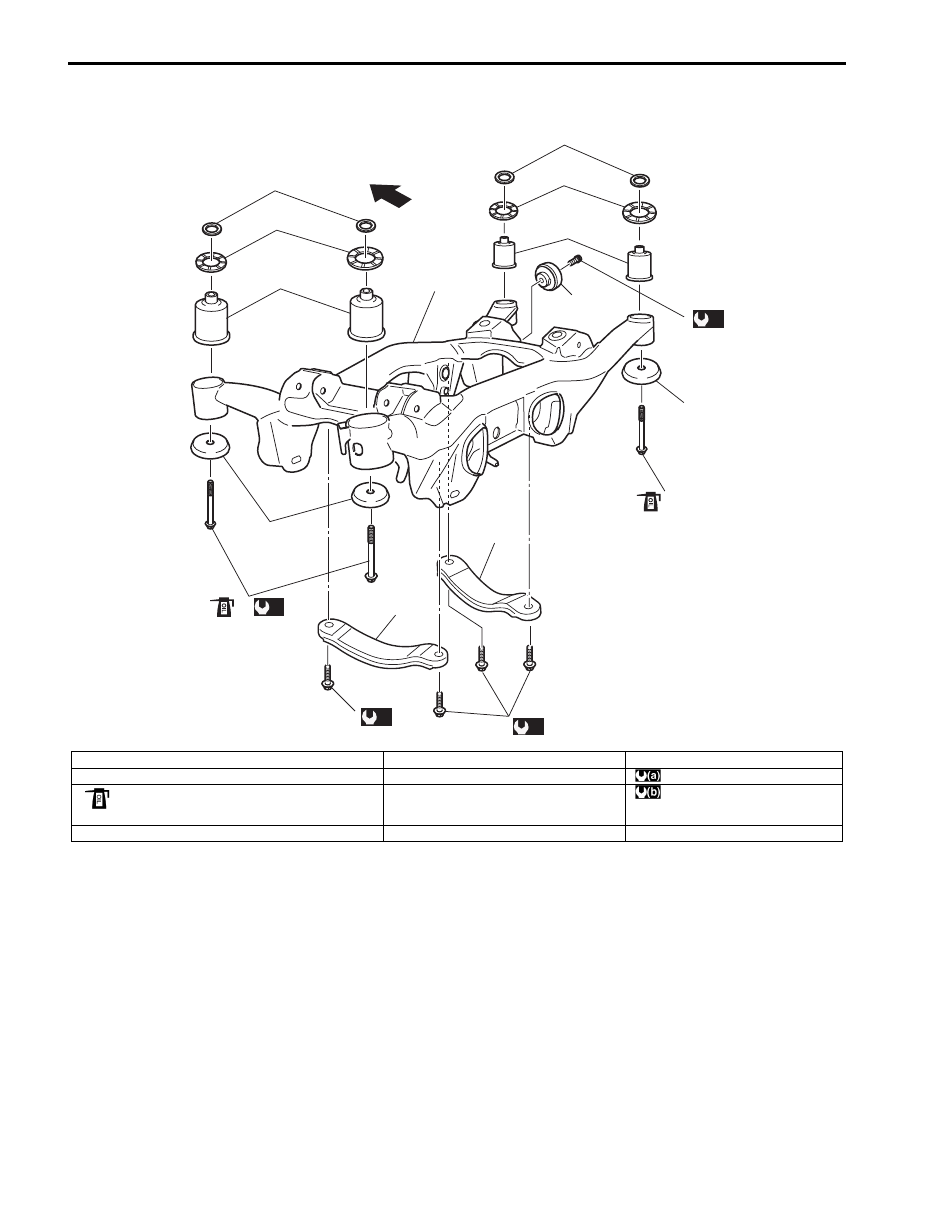
F: Forward
4. Rear suspension frame mount stopper
8. Stiffener
1. Rear suspension frame
5. Upper mount stopper washer
: 135 N
⋅m (13.5 kgf-m, 98.0 lb-ft)
2. Rear suspension frame mount bolt
: If reuse bolt, apply engine oil to thread, bearing and
trunk surface.
6. Rear suspension frame busing
: 50 N
⋅m (5.0 kgf-m, 36.5 lb-ft)
3. Rear suspension frame mount washer
7. Dynamic damper
Rear Suspension: 2C-21
Rear Suspension Frame Removal and
Installation
S5JB0A2306015
Removal
1) Hoist vehicle and remove rear wheels.
2) Remove muffler and exhaust center pipe referring to
“Exhaust System Components in Section 1K”.
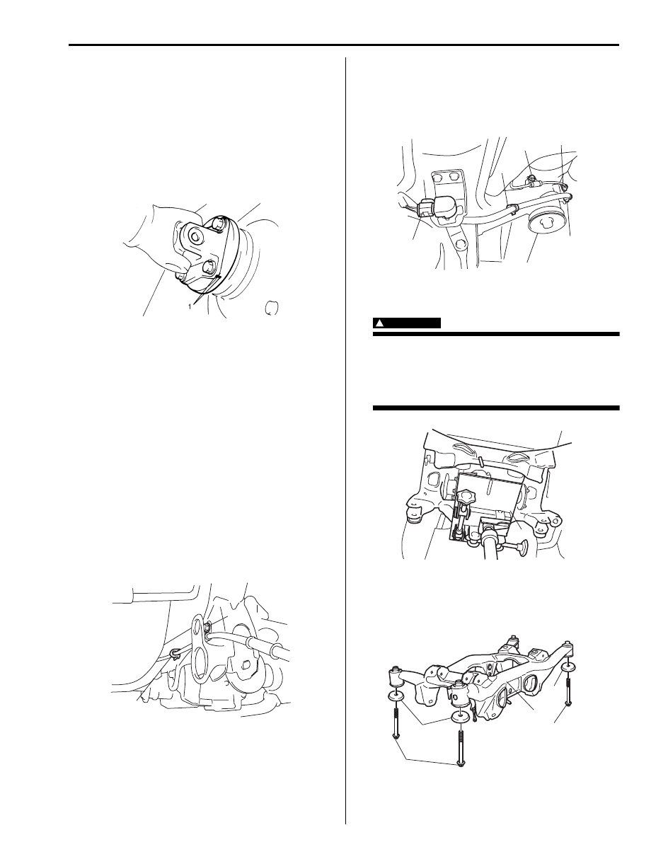
3) To facilitate reinstallation, put match marks (1) on
rear propeller shaft flange and differential flange.
Disconnect rear propeller shaft form differential.
4) Remove rear wheel hub assembly referring to “Rear
Wheel Hub Assembly Removal and Installation”.
5) Remove control rod referring to “Control Rod
6) Remove trailing rod referring to “Trailing Rod
7) Remove lower arm referring to “Lower Arm Removal
8) Remove rear drive shaft referring to “Rear Drive
Shaft Assembly Removal and Installation: Rear in
Section 3A”.
9) Remove rear suspension knuckle referring to “Rear
Suspension knuckle Removal and Installation”.
10) Remove upper arm referring to “Upper Arm Removal
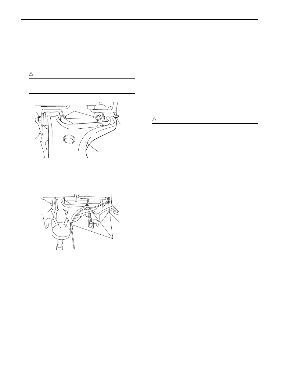
11) Remove parking cable clamp bolt (1) and parking
cable clamp (2).
12) Remove wheel sensor bolt (1) and ABS wheel
sensor harness clamp (2) (if equipped).
13) Disconnect rear height sensor connector (3) and
rear height sensor harness clamp (4) (if equipped)
for left side.
14) Support rear suspension frame with rear differential
by using mission jack (1).
WARNING
!
When removing rear suspension frame, be
sure to apply some supporting equipment
(such as mission jack) under it at well-
balanced position in the center section so as
to prevent from its drop.
15) Remove rear suspension frame mount bolts (1) and
washer (2) and then lower mission jack and remove
rear suspension frame (3) with rear differential and
rear suspension frame stopper (4).
16) Dismounting rear differential from rear suspension
frame referring to “Rear Differential Unit
Components: Rear in Section 3B”.
I3RH01232006-01
2
1
I5JB0A230047-01
4
3
4
1
4
2
I5JB0A230048-01
1
I5JB0A230049-01
2
2
3
1
1
I5JB0A230050-03
Нет комментариевНе стесняйтесь поделиться с нами вашим ценным мнением.
Текст