Suzuki Grand Vitara JB416 / JB420. Manual — part 274
7A-2 Heater and Ventilation:
Body Ventilation Construction
S5JB0A7101002
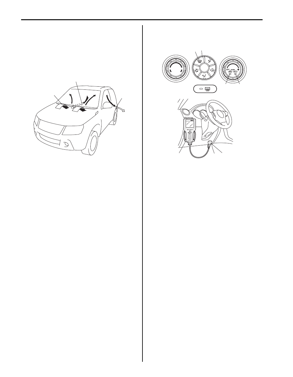
The body ventilation system of this vehicle has a fresh
air intake (1) located at the cowl top panel. When fresh
air intake air selector is at FRE position (fresh),
ventilating air is drawn into the interior from the cowl
center garnish and drawn out from the ventilator outlet
(2) provided at each side body outer panel (both right
and left side).
On-Board Diagnostic System Description (for
Vehicle without A/C)
S5JB0A7101004
HVAC control module (for vehicle without A/C) detects
malfunction, which may occur in the following area.
When HVAC control module detects any malfunction, the
REC (recirculation) indicator lamp (4) flashes on and off
continuously after turning ignition switch to ON position.
• ECT sensor
• CMP sensor
• Wheel speed sensor
• Temperature control actuator
• Air flow control actuator
• Air intake control actuator
• Temperature selector of HVAC control module
• Blower speed selector of HVAC control module
• Serial communication line
• CAN communication line
DTC can be checked by either one of the following ways.
• DTC can be checked by using SUZUKI scan tool (2)
connected to DLC (1).
• Without using SUZUKI scan tool, DTC can be
checked by reading the flashing pattern of both the
FRE (fresh) indicator lamp (3) and the REC
(recirculation) indicator lamp (4).
• Pressing DEF (defogger) switch (5) alternates display
of current DTC and history DTC.
• DEF indicator lamp (6) remains off when display is in
current DTC and it lights up when display is in history
DTC.
HVAC Control System Description (for Vehicle
without A/C)
S5JB0A7101005
For CAN communication system, refer to description on
“CAN Communication System Description in Section
1A”.
When following data are sent from control modules to
BCM through CAN communication, they are sent from
BCM to HVAC control module through serial
communication line.
• Engine coolant temperature
• Engine Speed
• Wheel speed (Vehicle speed)
HVAC control module has a function to make initial
settings of temperature control actuator, air intake
actuator and air flow actuator.
For vehicle without A/C, HVAC control module uses
engine speed signal so that temperature control
actuator, air intake actuator and air flow actuator can
make initial setting for door position.
Initial settings of actuators are automatically made when
engine is started for the first time after battery is
connected.
When initial settings are made, each actuator is forced to
operate for about 15 seconds continuously.
2
1
2
I5JB0A710002-03
3
4
5
6
1
2
I5JB0A710004-04

Heater and Ventilation: 7A-3
Schematic and Routing Diagram
Heater and Ventilation Wiring Circuit Diagram
S5JB0A7102001
Refer to “A/C System Wiring Circuit Diagram in Section 7B”.
Electronic Control Input / Output Diagram (for Vehicle without A/C)
S5JB0A7102003
Temperature selector
MODE (air flow) selector
Blower speed selector
Air intake selector
Wheel
speed
sensor
Blower motor controller
Temperature control actuator
Air flow control actuator
Air intake control actuator
BCM
ABS control module
Data link connector
HVAC control module
CPU
ECT sensor
ECM
CMP sensor
*
*
I5JB0A710003-05
*: CAN communication
7A-4 Heater and Ventilation:
Component Location
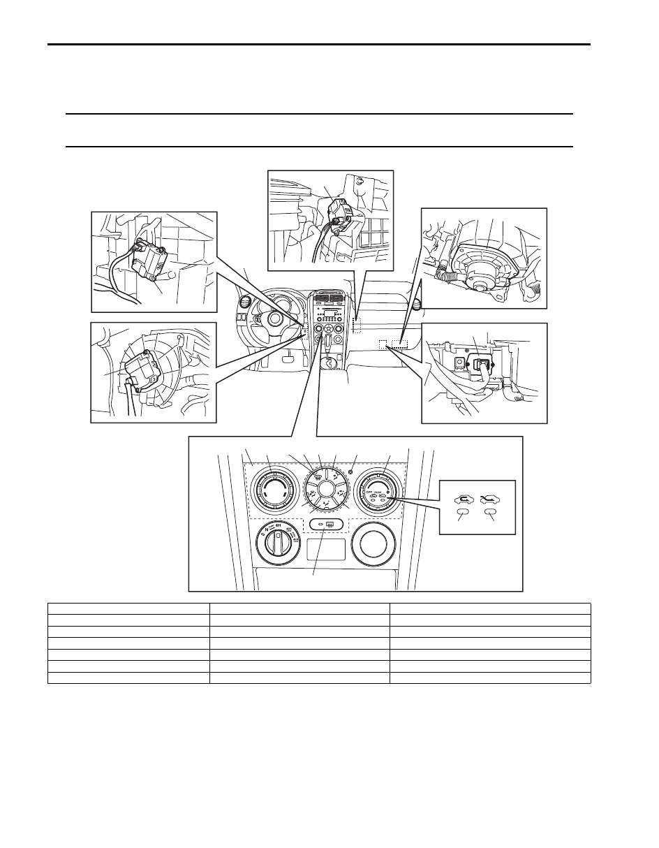
Electronic Components Location for Heater (for Vehicle without A/C)
S5JB0A7103001
NOTE
The figure shows left-hand steering vehicle. For right hand steering vehicle, parts with (*) are installed
at the opposite side.
2
3
1*
4*
5*
18
6
17
19
8
15
16
10
9
14
7
11
12
13
I5JB0A710005-07
1. Air intake control actuator
8. “DEF / FOOT” switch
15. “REC” indicator lamp
2. Temperature control actuator
9. “FOOT” switch
16. “FRE” indicator lamp
3. Air flow control actuator
10. “BI-LEVEL” switch
17. MODE selector
4. Blower motor
11. “VENT” switch
18. HVAC control module (for vehicle without A/C)
5. Blower motor controller
12. Theft deterrent light
19. “DEF” indicator lamp
6. Temperature selector
13. Blower speed selector / Air intake selector
7. “DEF” switch
14. Rear defogger switch

Heater and Ventilation: 7A-5
Diagnostic Information and Procedures
Heater and Ventilation System Check
S5JB0A7104009
Step
Action
Yes
No
1
Customer complaint analysis
1) Perform “Customer complaint analysis”.
Was customer complaint analysis performed?
Go to Step 2.
Perform customer
complaint analysis.
2
DTC check
1) Perform “DTC check”.
Is there any DTC code?
Go to Step 3.
Go to Step 4.
3
Troubleshooting malfunction
1) Perform “Troubleshooting malfunction”.
Is there any faulty condition?
Repair or replace
malfunction part, and go
to Step 7.
Go to Step 5.
4
Visual inspection
1) Perform “Visual inspection”.
Is there any faulty condition?
Repair or replace
malfunction part.
Go to Step 5.
5
Perform heater and ventilation system symptom
diagnosis
1) Inspect and repair referring to “Heater and Ventilation
Is there any faulty condition?
Repair or replace
malfunction part, and go
to Step 7.
Go to Step 6.
6
Check for intermittent problem
1) Check for intermittent troubles referring to “Intermittent
and Poor Connection Inspection in Section 00”.
Is there any faulty condition?
Repair or replace
malfunction part, and go
to Step 7.
Go to Step 7.
7
Final confirmation test
1) Perform “Final confirmation test”.
Is there any malfunction code?
Go to Step 4.
Heater and ventilation
system is in good
condition.
Нет комментариевНе стесняйтесь поделиться с нами вашим ценным мнением.
Текст