Suzuki Grand Vitara JB416 / JB420. Manual — part 272
6C-22 Power Assisted Steering System:
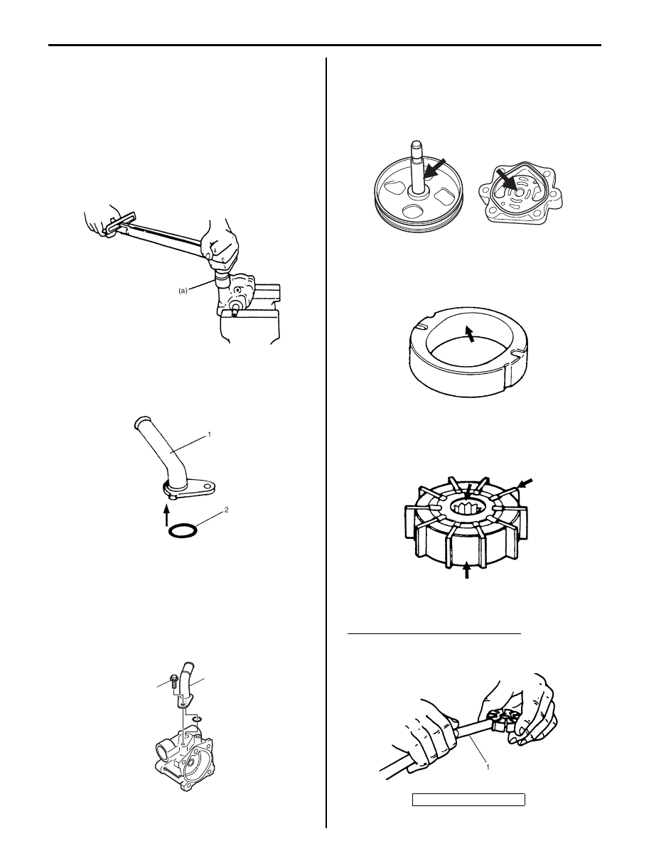
18) Apply power steering fluid to relief valve (flow control
valve).
19) Install relief valve (flow control valve) to pump body.
20) Install flow control spring.
21) Apply power steering fluid to O-rings of plug.
22) Install O-rings to plug.
23) Tighten plug to specified torque.
Tightening torque
Plug (a): 60 N·m (6.0 kgf-m, 43.5 lb-ft)
24) Apply power steering fluid to O-ring (2) of suction
connector (1).
25) Install O-ring (2) to suction connector (1).
26) Install suction connector (1) to pump body as shown
in the figure.
Tighten suction connector (1) bolts to specified
torque.
Tightening torque
Suction connector bolt for M16 engine model
(a): 12 N·m (1.2 kgf-m, 9.0 lb-ft)
P/S Pump Inspection for M16 Engine Model
S5JB0A6306014
Pump Body, Cover, Side Plate and Shaft
Check sliding surfaces of each part for wear and
damage. If any defect is found, replace pump assembly.
Cam Ring
Check vane sliding surface of cam ring for wear and
damage. If any defect is found, replace pump assembly.
Rotor and Vane
• Check sliding surfaces of rotor and vane for wear and
damage.
• Check clearance between rotor and vane. Replace
pump assembly if any defect is found.
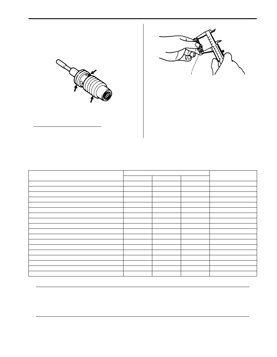
Clearance between rotor and vane
Standard: 0.015 mm (0.0006 in.)
Limit: 0.027 mm (0.0011 in.)
IYSQ01630051-01
IYSQ01630052-01
1
(a)
I5JB0A630038-02
1. Thickness gauge
I5JB0A630051-01
IYSQ01630055-01
IYSQ01630056-01
IYSQ01630057-01
Power Assisted Steering System: 6C-23
Relief Valve (Flow Control Valve) and Its Spring
• Check fluid passage of relief valve and orifice of
connector for obstruction (clogged).
• Check sliding surface of relief valve for wear and
damage.
• Check free length of relief valve spring (1). Replace if
any defective is found.
Free length of relief valve spring
Standard: 22.0 mm (0.866 in.)
Limit: 19.0 mm (0.748 in.)
P/S Pump Inspection for J20 Engine Model
S5JB0A6306026
Check P/S pump as follows.
• Damage of pump body.
• Oil leakage from pump body.
• Wear and damage of pulley.
• Abnormal noise when pulley is turned by hand.
If abnormality is found, replace P/S pump with new one.
Specifications
Tightening Torque Specifications
S5JB0A6307001
NOTE
The specified tightening torque is also described in the following.
“P/S Gear Case Assembly Components”
“P/S Hose / Pipe Components”
“P/S Pump Components for M16 Engine Model”
“P/S Pump Assembly Components for J20 Engine Model”
Reference:
For the tightening torque of fastener not specified in this section, refer to “Fastener Information in Section 0A”.
IYSQ01630058-01
IYSQ01630059-01
Fastening part
Tightening torque
Note
N
⋅m
kgf-m
lb-ft
P/S belt tension pulley bolt
25
2.5
18.5
P/S belt tension pulley nut
25
2.5
18.5
Tie-rod end nut
43
4.3
31.0
Wheel nut
100
10.0
72.5
Tie-rod end lock nut
65
6.5
47.0
Steering lower shaft bolt
25
2.5
18.5
Gear case high pressure pipe union bolt
35
3.5
25.5
Gear case cylinder pipe flare nut
25
2.5
18.0
Gear case mounting bolt
105
10.5
76
Gear case low pressure pipe union bolt
40
4.0
29.0
Stabilizer bar mount bracket mount bolt
60
6.0
43.0
Tie-rod ball nut
90
9.0
65.0
P/S pump mounting bolt
25
2.5
18.0
High pressure pipe union bolt
60
6.0
43.5
P/S pump cover bolt
28
2.8
20.5
Pressure switch for M16 engine model
28
2.8
20.5
Plug
60
6.0 43.5
Suction connector bolt for M16 engine model
12
1.2
9.0
6C-24 Power Assisted Steering System:
Special Tools and Equipment
Recommended Service Material
S5JB0A6308001
NOTE
Required service material is also described in the following.
“P/S Gear Case Assembly Components”
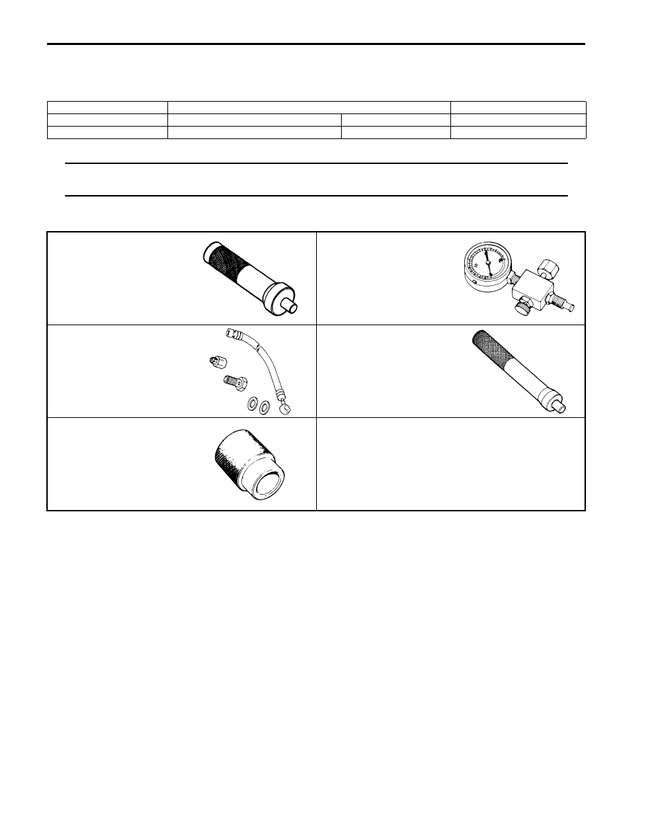
Special Tool
S5JB0A6308002
Material
SUZUKI recommended product or Specification
Note
Grease
SUZUKI Super Grease A
P/No.: 99000–25010
Thread lock cement
Thread Lock Cement 1305
P/No.: 99000–32100
09913–75821
09915–77412
Bearing installer attachment
Oil pressure gauge
09915–77420
09943–88211
Oil pressure gauge
attachment and hose set
Pinion bearing installer
09945–55410
Bushing installer
)
Table of Contents 7- i
7
Section 7
CONTENTS
HVAC
Precautions . . . . . . . . . . . . .7-1
Precautions. . . . . . . . . . . . . . . . 7-1
Precautions for HVAC. . . . . . . . . . ... 7-1
Heater and Ventilation. . . . . . . . 7A-1
General Description . . . . . . . . . . . .7A-1
Heater and Ventilation Construction . . . . ... 7A-1
Body Ventilation Construction. . . . . . . . 7A-2
On-Board Diagnostic System Description (for
Vehicle without A/C). . . . . . . . . . .. 7A-2
HVAC Control System Description (for
Vehicle without A/C). . . . . . . . . . .. 7A-2
Schematic and Routing Diagram. . . . . . 7A-3
Heater and Ventilation Wiring Circuit Diagram . 7A-3
Electronic Control Input / Output Diagram (for
Vehicle without A/C). . . . . . . . . . .. 7A-3
Component Location . . . . . . . . . . ...7A-4
Electronic Components Location for Heater
(for Vehicle without A/C) . . . . . . . . ... 7A-4
Diagnostic Information and Procedures. . . 7A-5
Heater and Ventilation System Check . . . . 7A-5
Visual Inspection. . . . . . . . . . . . . 7A-7
DTC Check . . . . . . . . . . . . . . . 7A-7
DTC Clearance . . . . . . . . . . . . ... 7A-7
DTC Table. . . . . . . . . . . . . . ... 7A-7
Fail-Safe Table. . . . . . . . . . . . . 7A-7
Scan Tool Data . . . . . . . . . . . . ... 7A-7
Heater and Ventilation Symptom Diagnosis. . 7A-8
Repair Instructions . . . . . . . . . . . ..7A-9
Blower Unit and Heater Unit Components . . .. 7A-9
HVAC Unit Removal and Installation (for
Vehicle without A/C). . . . . . . . . . .. 7A-9
HVAC Air Filter Removal and Installation (for
Vehicle without A/C). . . . . . . . . . .. 7A-9
HVAC Air Filter Inspection (for Vehicle without
A/C). . . . . . . . . . . . . . . . ... 7A-9
Blower Motor Removal and Installation. . . ... 7A-9
Blower Motor Inspection . . . . . . . . . . 7A-9
Blower Motor Controller Removal and
Installation. . . . . . . . . . . . . ...7A-10
Blower Motor Controller Inspection . . . . ...7A-10
Blower Motor Relay Inspection . . . . . . .7A-10
Heater Core Removal and Installation . . . .. 7A-11
HVAC Control Module Removal and
Installation . . . . . . . . . . . . . ...7A-11
HVAC Control Module and Its Circuits
Inspection (for Vehicle without A/C) . . . . 7A-11
Air Flow Control Actuator Removal and
Installation . . . . . . . . . . . . . ...7A-11
Air Flow Control Actuator Inspection. . . . .7A-11
Temperature Control Actuator Removal and
Installation . . . . . . . . . . . . . ...7A-12
Temperature Control Actuator Inspection . . .7A-12
Air Intake Control Actuator Removal and
Installation . . . . . . . . . . . . . ...7A-13
Air Intake Control Actuator Inspection. . . ...7A-13
Actuator Linkage Inspection. . . . . . . ..7A-13
Center Ventilation Louver Removal and
Installation . . . . . . . . . . . . . ...7A-14
Side Ventilation Louver Removal and
Installation . . . . . . . . . . . . . ...7A-14
Rear Duct Components. . . . . . . . . .7A-15
Rear Duct Removal and Installation. . . . ..7A-15
Air Conditioning System. . . . . . . 7B-1
Precautions. . . . . . . . . . . . . . ...7B-1
134a (R-134a) . . . . . . . . . . . . ...7B-1
Precautions on Servicing Refrigerant Line. . ..7B-2
Precautions on Refrigerant Recovery . . . . .7B-3
Precautions on Refrigerant Charge. . . . . .7B-3
Precautions on Replenishing Compressor Oil . 7B-3
Precautions on Servicing Compressor
Assembly. . . . . . . . . . . . . . ...7B-4
General Description . . . . . . . . . . . .7B-4
AUTO A/C System Description . . . . . . ...7B-4
HVAC Control System Description. . . . . ..7B-4
HVAC Control Module Operation Description . .7B-5
A/C Refrigerant Type Description . . . . . ...7B-5
Sub-Cool A/C System Description . . . . . ..7B-6
A/C Evaporator Temperature Sensor
Description . . . . . . . . . . . . . . 7B-7
On-Board Diagnostic System Description. . ...7B-7
Нет комментариевНе стесняйтесь поделиться с нами вашим ценным мнением.
Текст