Suzuki Grand Vitara JB416 / JB420. Manual — part 64

1A-205 Engine General Information and Diagnosis:
DTC Confirmation Procedure
1) With ignition switch turned OFF, connect scan tool.
2) Turn ON ignition switch and clear DTC using scan tool.
3) Keep the accelerator pedal at idle position for 2 seconds.
4) Keep the accelerator pedal at fully depressed position for 2 seconds.
5) Repeat Step 3) and 4) for 3 times.
6) Check DTC.
DTC Troubleshooting
NOTE
Before this trouble shooting is performed, read the precautions for DTC troubleshooting referring to
“Precautions For DTC Troubleshooting”.
Step
Action
Yes
No
1
Was “Engine and Emission Control System Check”
performed?
Go to Step 2.
Go to “Engine and
Emission Control
System Check”.
2
Accelerator pedal position (APP) sensor assembly
mounting check
1) Check that accelerator pedal position (APP) sensor
assembly has been mounted to vehicle body properly
(no pinched floor carpet, etc).
Is it OK?
Go to Step 3.
Reinstall accelerator
pedal position (APP)
sensor assembly
properly referring to
“Accelerator Pedal
Position (APP) Sensor
Assembly Removal and
Installation in Section
1C”.
3
Accelerator pedal position sensor (sub) and its circuit
check
1) Connect scan tool to DLC with ignition switch turned
OFF.
2) Turn ON ignition switch, check “APP Sensor 2 Volt”
displayed on scan tool.
Is displayed voltage 4.8 V or more?
Go to Step 4.
Intermittent trouble.
Check for intermittent
referring to “Intermittent
and Poor Connection
Inspection in Section
00”.
4
ECM voltage check
1) Disconnect connector from accelerator pedal position
(APP) sensor assembly with ignition switch turned OFF.
2) Check for proper connection to accelerator pedal
position (APP) sensor assembly at “ORN/BLU”, “BLU/
GRN” and “BLU/YEL” wire terminals.
3) If OK, measure voltage between “ORN/BLU” wire
terminal of accelerator pedal position (APP) sensor
assembly connector and vehicle body ground with
ignition switch turned ON.
Is voltage 4 – 6 V?
Go to Step 6.
Go to Step 5.
“BLU/GRN”
“BLU/YEL”
“ORN”
“WHT/BLU”
“WHT”
“ORN BLU”
I5JB0A110071-01

Engine General Information and Diagnosis: 1A-206
5
Wire harness check
1) Disconnect connectors from ECM with ignition switch
turned OFF.
2) Check for proper connection of ECM connector at “E23-
53” terminal.
3) If OK, measure voltage between “E23-53” terminal of
ECM connector and engine ground with ignition switch
turned ON.
Is voltage 0 V?
Substitute a known-
good ECM and recheck.
“ORN/BLU” wire is
shorted to power circuit.
6
Wire harness check
1) Disconnect connectors from ECM with ignition switch
turned OFF.
2) Check for proper connection of ECM connector at “E23-
56”, “E23-53” and “E23-52” terminals.
3) If OK, measure resistance between “BLU/GRN” wire
terminal and each “WHT”, “ORN/BLU” wire terminals of
accelerator pedal position (APP) sensor assembly
connector.
Is each resistance infinity?
Go to Step 7.
“BLU/GRN” wire is
shorted to “WHT” wire
and/or “ORN/BLU” wire.
7
Wire harness check
1) Turn ON ignition switch.
2) Measure voltage between “E23-52” terminal of ECM
connector and engine ground.
Is voltage 0 V?
Go to Step 8.
“BLU/GRN” wire is
shorted to power circuit.
8
Ground circuit check
1) Connect connectors to ECM with ignition switch turned
OFF.
2) Measure resistance between “BLU/YEL” wire terminal of
accelerator pedal position (APP) sensor assembly
connector and vehicle body ground.
Is resistance below 3
Ω
?
Go to Step 10.
Go to Step 9.
9
Ground circuit check
1) Remove ECM from its bracket with ECM connectors
connected.
2) Check for proper connection of ECM connector at “E23-
51” terminal.
3) If OK, measure resistance between “E23-51” terminal of
ECM connector and engine ground.
Is resistance below 3
Ω
?
“BLU/YEL” wire is open
or high resistance
circuit.
Faulty ECM ground
circuit. If circuit is OK,
substitute a known-
good ECM and recheck.
10 Accelerator pedal position (APP) sensor assembly
check
1) Check accelerator pedal position sensor (sub) referring
to “Accelerator Pedal Position (APP) Sensor Assembly
Inspection in Section 1C”.
Is output voltage within specified value?
Substitute a known-
good ECM and recheck.
Replace accelerator
pedal position (APP)
sensor assembly.
Step
Action
Yes
No
1A-207 Engine General Information and Diagnosis:
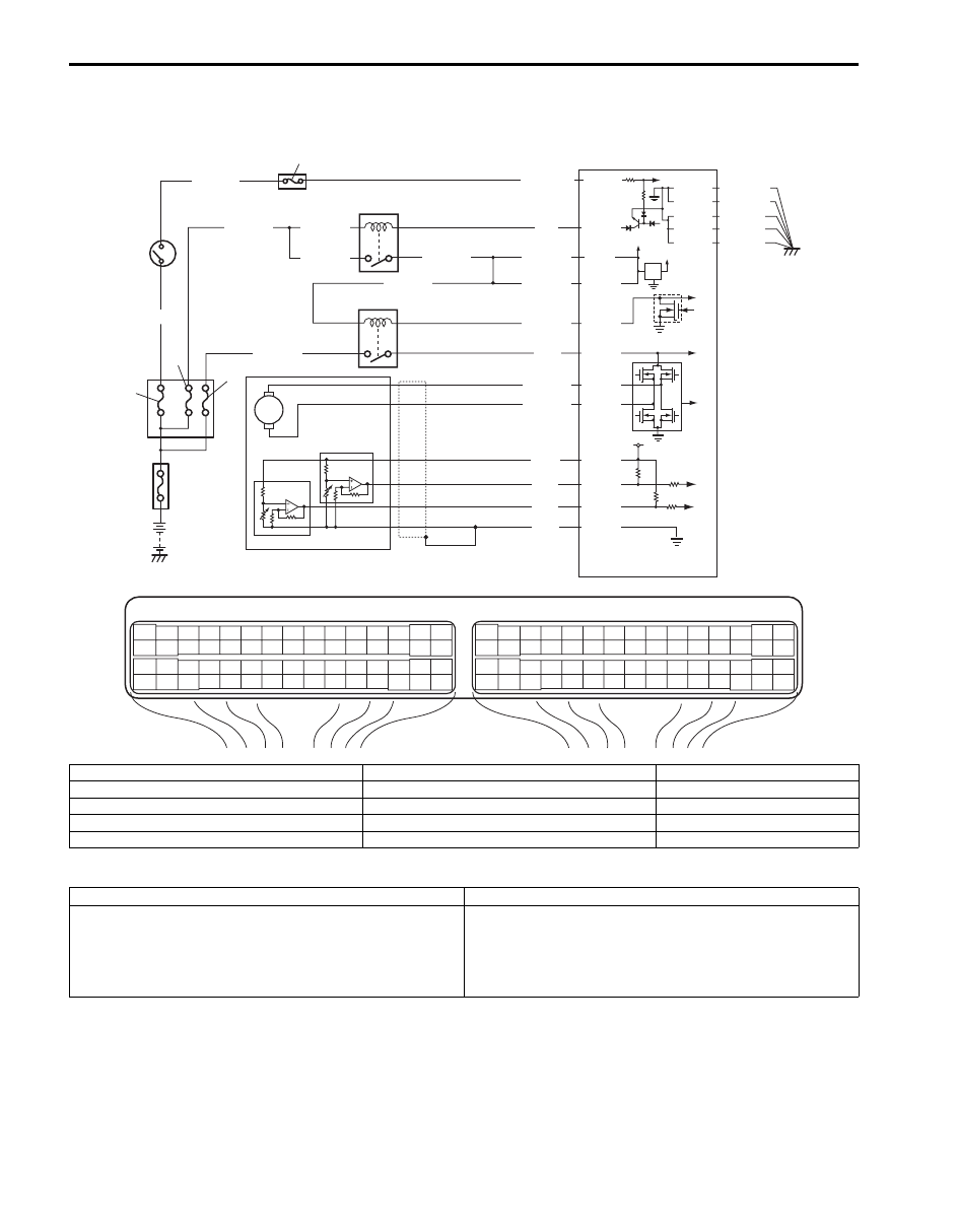
DTC P2135: Throttle Position Sensor (Main / Sub) Voltage Correlation
S5JB0A1104086
Wiring Diagram
DTC Detecting Condition and Trouble Area
DTC Confirmation Procedure
1) With ignition switch turned OFF, connect scan tool.
2) Turn ON ignition switch and clear DTC using scan tool.
3) Keep the accelerator pedal at idle position for 2 seconds.
4) Keep the accelerator pedal at fully depressed position for 2 seconds.
5) Repeat Step 3) and 4) for 3 times.
6) Check DTC.
E23
C37
3
4
18
19
5
6
7
10
11
17
20
47
46
49
50
51
21
22
52
16
25
9
24
14
29
55
57
54 53
59
60
58
2
26
27
28
15
30
56
48
32
31
34
35
36
37
40
42
39 38
44
45
43
41
33
1
12
13
23
8
3
4
18
19
5
6
7
10
11
17
20
47
46
49
50
51
21
22
52
16
25
9
24
14
29
55
57
54 53
59
60
58
2
26
27
28
15
30
56
48
32
31
34
35
36
37
40
42
39 38
44
45
43
41
33
1
12
13
23
8
12V
5V
BLU/BLK
BLU/BLK
BLK/RED
1
2
BLK/RED
BLK/RED
BLU
E23-1
E23-60
C37-15
C37-29
C37-48
BLK/ORN
C37-58
BLU/ORN
GRN
BLU/RED
BLU/YEL
BLU/RED
E23-16
E23-50
E23-17
C37-45
C37-44
1-1
1-2
1-3
3
4
5
8
6
7
10
9
E23-29
BLK/YEL
BLK/WHT
WHT/GRN
C37-30 BLK/ORN
BLK/YEL
BLK/YEL
BLK/YEL
BLU/BLK
BLU/BLK
WHT
BLK
RED
GRN
C37-53
C37-54
C37-40
C37-41
I5JB0A110072-01
1. Electric throttle body assembly
3. ECM
8. “IGN” fuse
1-1. Throttle actuator
4. Main relay
9. “IG COIL” fuse
1-2. Throttle position sensor (main)
5. Fuse box No.2
10. Ignition switch
1-3. Throttle position sensor (sub)
6. “THR MOT” fuse
2. Throttle actuator control relay
7. “FI” fuse
DTC detecting condition
Trouble area
Difference between the opening angle based on throttle
position sensor (main) and the opening angle based on
throttle position sensor (sub) is more than specification for
specified time continuously.
(1 driving detection logic)
• Throttle position sensor (main) and (sub) circuit
• Electric throttle body assembly
• ECM
Engine General Information and Diagnosis: 1A-208
DTC Troubleshooting
NOTE
Before this trouble shooting is performed, read the precautions for DTC troubleshooting referring to
“Precautions For DTC Troubleshooting”.
Step
Action
Yes
No
1
Was “Engine and Emission Control System Check”
performed?
Go to Step 2.
Go to “Engine and
Emission Control
System Check”.
2
Throttle position sensor and its circuit check
1) Connect scan tool to DLC with ignition switch turned
OFF.
2) Turn ON ignition switch, check each voltage of “TP
Sensor 1 Volt” and “TP Sensor 2 Volt” displayed on scan
tool when accelerator pedal is idle position and fully
depressed.
Is displayed each TP sensor value as described voltage in
“Scan Tool Data”?
Intermittent trouble.
Check for intermittent
referring to “Intermittent
and Poor Connection
Inspection in Section
00”.
Go to Step 3.
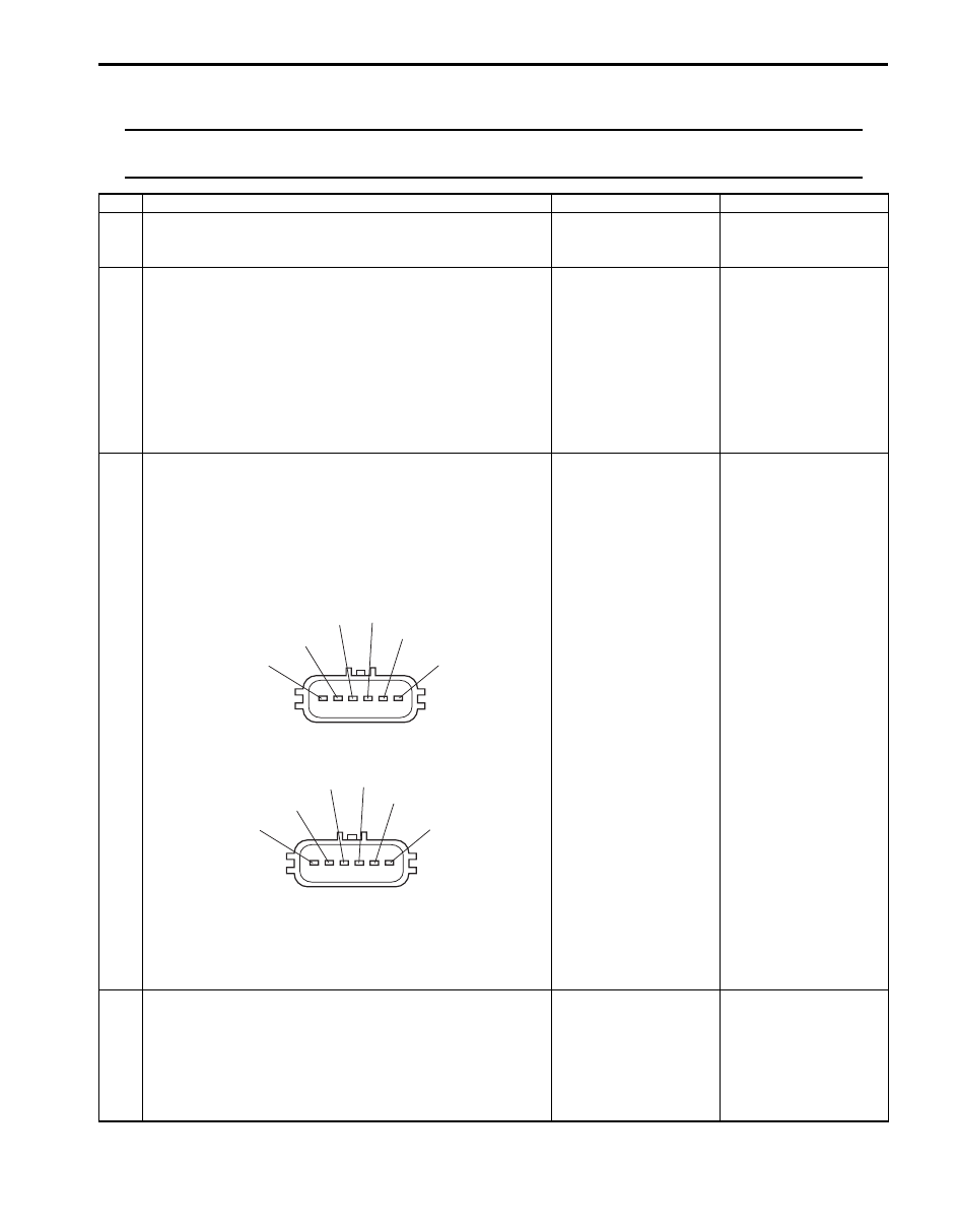
3
ECM voltage check
1) Disconnect connector from electric throttle body
assembly with ignition switch turned OFF.
2) Check for proper connection to electric throttle body
assembly at “RED”, “GRN”, “WHT” and “BLK” wire
terminals.
For J20 engine
For M16 engine
3) If OK, measure voltage between “WHT” wire terminal of
electric throttle body assembly connector and engine
ground with ignition switch turned ON.
Is voltage 4 – 6 V?
Go to Step 6.
Go to Step 4.
4
Wire harness check
1) Disconnect connectors from ECM with ignition switch
turned OFF.
2) Measure resistance between “C37-53” terminal of ECM
connector and engine ground.
Is resistance infinity?
Go to Step 5.
“WHT” wire is shorted to
other circuit.
"BLK"
"WHT"
"RED"
"GRN"
"BLU/YEL"
"BLU/RED"
I5JB0A110042-01
"BLU/RED"
"BLU/YEL"
"GRN"
"RED"
"WHT"
"BLK"
I5JB0A110043-01
Нет комментариевНе стесняйтесь поделиться с нами вашим ценным мнением.
Текст