Suzuki Grand Vitara JB416 / JB420. Manual — part 65

1A-209 Engine General Information and Diagnosis:
5
Wire harness check
1) Measure voltage between “C37-53” terminal of ECM
connector and engine ground with ignition switch turned
ON.
Is voltage 0 V?
Substitute a known-
good ECM and recheck.
“WHT” wire is shorted to
other circuit.
6
Wire harness check
1) Measure voltage between “BLK” wire terminal of electric
throttle body assembly connector and engine ground,
between “RED” wire terminal of electric throttle body
assembly connector and engine ground with ignition
switch turned ON.
Is each voltage 4 – 6 V?
Go to Step 9.
Go to Step 7.
7
Wire harness check
1) Turn OFF ignition switch.
2) Disconnect connectors from ECM.
3) Check for proper connection of ECM connector at “C37-
54” and “C37-40” terminals.
4) If OK, measure voltage between “C37-54” terminal of
ECM connector and engine ground, between “C37-40”
terminal of ECM connector and engine ground.
Is each voltage 0 V?
Go to Step 8.
“BLK” wire or “RED”
wire is shorted to other
circuit.
8
Wire harness check
1) Measure resistance between “BLK” wire terminal of
electric throttle body assembly connector and engine
ground, between “RED” wire terminal of electric throttle
body assembly connector and engine ground with
ignition switch turned OFF.
Is each resistance infinity?
Substitute a known-
good ECM and recheck.
“BLK” wire or “RED”
wire is shorted to other
circuit.
9
Electric throttle body assembly check
1) Check throttle position sensor referring to “Throttle
Position Sensor Performance Check” under “Electric
Throttle Body Assembly On-Vehicle Inspection in
Section 1C”.
Is each output voltage within specified value?
Substitute a known-
good ECM and recheck.
Replace electric throttle
body assembly.
Step
Action
Yes
No
Engine General Information and Diagnosis: 1A-210
DTC P2138: Pedal Position Sensor (Main / Sub) Voltage Correlation
S5JB0A1104087
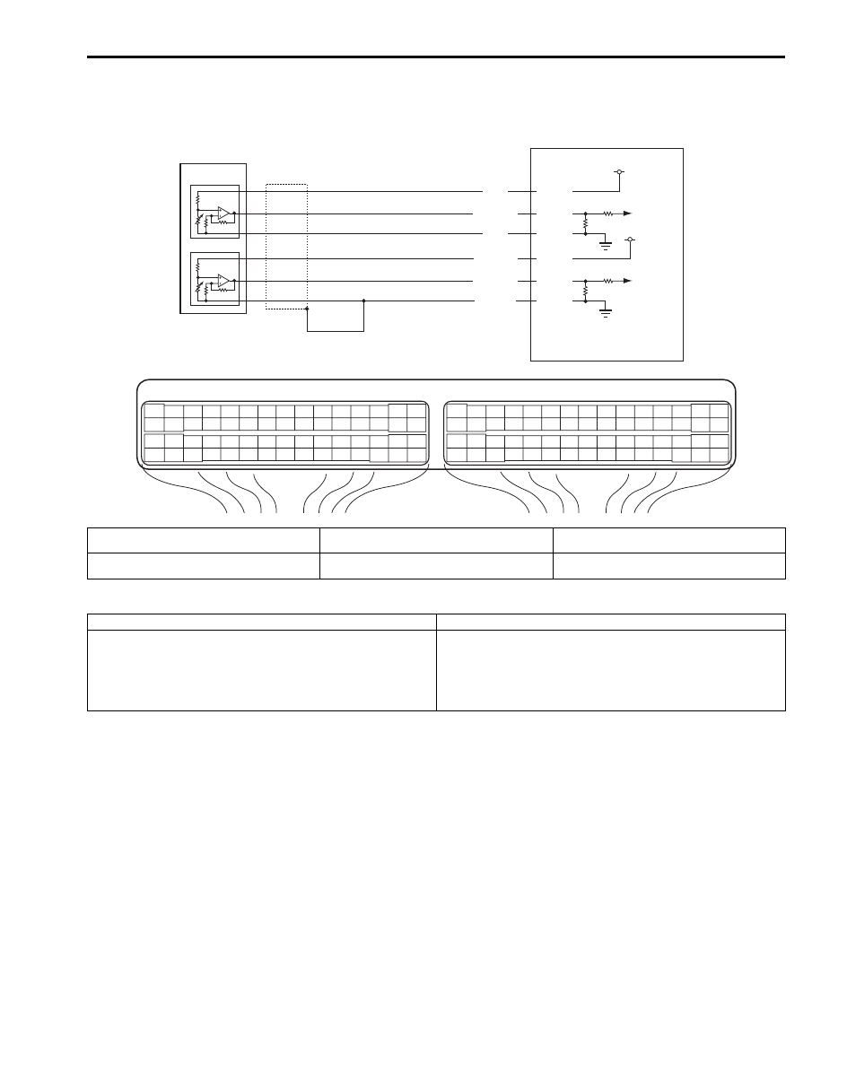
Wiring Diagram
DTC Detecting Condition and Trouble Area
DTC Confirmation Procedure
1) With ignition switch turned OFF, connect scan tool.
2) Turn ON ignition switch and clear DTC using scan tool.
3) Keep the accelerator pedal at idle position for 2 seconds.
4) Keep the accelerator pedal at fully depressed position for 2 seconds.
5) Repeat Step 3) and 4) for 3 times.
6) Check DTC.
E23
C37
3
4
18
19
5
6
7
10
11
17
20
47
46
49
50
51
21
22
52
16
25
9
24
14
29
55
57
54 53
59
60
58
2
26
27
28
15
30
56
48
32
31
34
35
36
37
40
42
39 38
44
45
43
41
33
1
12
13
23
8
3
4
18
19
5
6
7
10
11
17
20
47
46
49
50
51
21
22
52
16
25
9
24
14
29
55
57
54 53
59
60
58
2
26
27
28
15
30
56
48
32
31
34
35
36
37
40
42
39 38
44
45
43
41
33
1
12
13
23
8
E23-56
E23-55
E23-54
E23-53
E23-52
E23-51
5 V
5 V
WHT
WHT/BLU
ORN
ORN/BLU
BLU/GRN
BLU/YEL
1
1-1
3
2
1-2
I5JB0A110070-01
1. Accelerator pedal position (APP) sensor
assembly
1-2. Accelerator pedal position (APP) sensor (sub)
3. Ground of accelerator pedal position (APP)
sensor for shield wire
1-1. Accelerator pedal position (APP) sensor
(main)
2. ECM
DTC detecting condition
Trouble area
Difference between the opening angle based on
accelerator pedal position sensor (main) and the opening
angle based on accelerator pedal position sensor (sub) is
more than specification for specified time continuously.
(1 driving detection logic)
• Accelerator pedal position (APP) sensor (main) and
(sub) circuit
• Accelerator pedal position (APP) sensor assembly
• ECM
1A-211 Engine General Information and Diagnosis:
DTC Troubleshooting
NOTE
Before this trouble shooting is performed, read the precautions for DTC troubleshooting referring to
“Precautions For DTC Troubleshooting”.
Step
Action
Yes
No
1
Was “Engine and Emission Control System Check”
performed?
Go to Step 2.
Go to “Engine and
Emission Control
System Check”.
2
Accelerator pedal position sensor and its circuit check
1) Connect scan tool to DLC with ignition switch turned
OFF.
2) Turn ON ignition switch.
3) Check each voltage of “APP Sensor 1 Volt” and “APP
Sensor 2 Volt” displayed on scan tool when accelerator
pedal is idle position and fully depressed.
Is displayed each APP sensor value as described voltage in
“Scan Tool Data”?
Intermittent trouble.
Check for intermittent
referring to “Intermittent
and Poor Connection
Inspection in Section
00”
Go to Step 3.
3
ECM voltage check
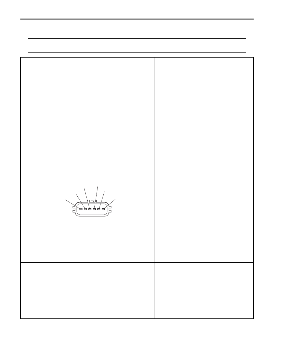
1) Disconnect connector from accelerator pedal position
(APP) sensor assembly with ignition switch turned OFF.
2) Check for proper connection to accelerator pedal
position (APP) sensor assembly at “BLU/YEL”, “BLU/
GRN”, “ORN/BLU”, “ORN”, “WHT/BLU” and “WHT” wire
terminals.
3) If OK, measure voltage between “WHT” wire terminal of
accelerator pedal position (APP) sensor assembly
connector and vehicle body ground, between “ORN/
BLU” wire terminal of accelerator pedal position (APP)
sensor assembly connector and vehicle body ground
with ignition switch turned ON.
Is each voltage 4 – 6 V?
Go to Step 6.
Go to Step 4.
4
Wire harness check
1) Disconnect connectors from ECM with ignition switch
turned OFF.
2) Check for proper connection of ECM connector at “E23-
56” and “E23-53” terminals.
3) If OK, measure resistance between “E23-56” terminal of
ECM connector and engine ground, between “E23-53”
terminal of ECM connector and engine ground.
Is each resistance infinity?
Go to Step 5.
“WHT” wire or “ORN/
BLU” wire is shorted to
other circuit.
“BLU/GRN”
“BLU/YEL”
“ORN”
“WHT/BLU”
“WHT”
“ORN BLU”
I5JB0A110071-01

Engine General Information and Diagnosis: 1A-212
DTC P2227 / P2228 / P2229: Barometric Pressure Circuit Malfunction
S5JB0A1104062
DTC P2227: Barometric Pressure Circuit Range / Performance
DTC P2228: Barometric Pressure Circuit Low
DTC P2229: Barometric Pressure Circuit High
System Description
Barometric pressure sensor is installed in ECM.
DTC Detecting Condition and Trouble Area
5
Wire harness check
1) Measure voltage between “E23-56” terminal of ECM
connector and engine ground, between “E23-53”
terminal of ECM connector and engine ground with
ignition switch turned ON.
Is each voltage 0 V?
Substitute a known-
good ECM and recheck.
“WHT” wire or “ORN/
GRN” wire is shorted to
other circuit.
6
Wire harness check
1) Disconnect connectors from ECM with ignition switch
turned OFF.
2) Check for proper connection of ECM connector at “E23-
55”, “E23-54”, “E23-52” and “E23-51” terminals.
3) If OK, measure resistance between “WHT/BLU” wire
terminal of accelerator pedal position (APP) sensor
assembly connector and vehicle body ground, between
“BLU/GRN” wire terminal of accelerator pedal position
(APP) sensor assembly connector and vehicle body
ground.
Is each resistance infinity?
Go to Step 7.
“WHT/BLU” wire or
“BLU/GRN” wire is
shorted to other circuit.
7
Wire harness check
1) Turn ON ignition switch.
2) Measure voltage between “E23-55” terminal of ECM
connector and engine ground, between “E23-52”
terminal of ECM connector and engine ground.
Is each voltage 0 V?
Go to Step 8.
“WHT/BLU” wire or
“BLU/GRN” wire is
shorted to other circuit.
8
Accelerator pedal position (APP) sensor assembly
check
1) 1)Check accelerator pedal position sensor referring to
“Accelerator Pedal Position (APP) Sensor Assembly
Inspection in Section 1C”.
Is output voltage within specified value?
Substitute a known-
good ECM and recheck.
Replace accelerator
pedal position (APP)
sensor assembly.
Step
Action
Yes
No
DTC detecting condition
Trouble area
DTC P2227:
Difference of barometric pressure value and intake manifold
pressure value is higher than specified value while engine
cranking.
(2 driving cycle detection logic)
• Manifold absolute pressure sensor
performance problem
• Barometric pressure sensor in ECM
DTC P2228:
Barometric pressure signal less than specified value is detected.
(1 driving cycle detection logic)
• Barometric pressure sensor in ECM
DTC P2229:
Barometric pressure signal more than specified value is detected.
(1 driving cycle detection logic)
Нет комментариевНе стесняйтесь поделиться с нами вашим ценным мнением.
Текст