Suzuki Grand Vitara JB416 / JB420. Manual — part 295

7B-71 Air Conditioning System:
Expansion Valve Removal and Installation
S5JB0A7206017
Removal
1) Recover refrigerant from the A/C system with
recovery and recycling equipment referring to
“Recovery” in “Operation Procedure for Charging A/
C with Refrigerant”.
2) Loosen a bolt (1) and remove pipes from expansion
valve (2).
3) Loosen bolts (3) and remove expansion valve.
Installation
1) Reverse removal nothing the following instructions.
• Apply compressor oil to O-ring of expansion valve
and pipes.
2) Evacuate and charge system according to
“Operation Procedure for Charging A/C with
Refrigerant”.
A/C Refrigerant Pressure Sensor and Its Circuit
Inspection
S5JB0A7206051
1) Disconnect A/C refrigerant pressure sensor
connector.
2) Turn ignition switch to ON position.
3) Check if voltage between “GRY/RED” wire terminal
and “GRY/GRN” wire terminal of A/C refrigerant
pressure sensor connector is 4.75 V to 5.25 V.
If not, check A/C refrigerant pressure sensor circuit.
4) Connect A/C refrigerant pressure sensor connector
with ignition switch turned OFF.
5) Connect manifold gauge set to the charging valves.
6) Check A/C refrigerant pressure sensor voltage of
ECM connector referring to “A/C System Inspection
at ECM”.
If voltage is not as specified below, replace A/C
refrigerant pressure sensor.
A/C refrigerant pressure sensor voltage
specifications (A/C refrigerant pressure measured
by manifold gauge)
0.8 MPa (8.0 kg/cm
2
, 116 psi): Approx. 1.46 – 1.71 V
1.4 MPa (14 kg/cm
2
, 203 psi): Approx. 2.28 – 2.53 V
1.6 MPa (16 kg/cm
2
, 232 psi): Approx. 2.55 – 2.80 V
1.8 MPa (18 kg/cm
2
, 261 psi): Approx. 2.82 – 3.03 V
3
1
2
2
I5JB0A720048-02

Air Conditioning System: 7B-72
A/C Refrigerant Pressure Sensor Removal and
Installation
S5JB0A7206050
Removal
1) Recover refrigerant from the A/C system with the
recovery and recycling equipment referring to
“Recovery” in “Operation Procedure for Charging A/
C with Refrigerant”.
2) Disconnect negative (–) cable from battery.
3) Disconnect A/C refrigerant pressure sensor
connector.
4) Remove A/C refrigerant pressure sensor (1) from
liquid pipe (2).
Installation
Reverse removal procedure noting the following
instructions.
• Apply compressor oil to O-ring of A/C refrigerant
pressure sensor.
• Tighten A/C refrigerant pressure sensor (1) to
specified torque.
Tightening torque
A/C refrigerant pressure sensor (a): 11 N·m (1.1
kgf-m, 8.0 lb-ft)
• Evacuate and charge the A/C system referring to
“Evacuation” and “Charge” in “Operation Procedure
for Charging A/C with Refrigerant”.
Sunload Sensor Removal and Installation
S5JB0A7206052
Removal
1) Disconnect negative (–) cable at battery.
2) Detach sunload sensor (1) located on the driver side
of the dashboard (3). Be careful not to damage the
sensor and dashboard by using rag (2).
3) Disconnect connector (1) from sunload sensor (2).
Installation
Reverse removal procedure.
1
2
I5JB0A720049-03
1, (a)
I5JB0A720050-03
2
1
3
I5JB0A720051-01
1
2
I5JB0A720052-01
7B-73 Air Conditioning System:
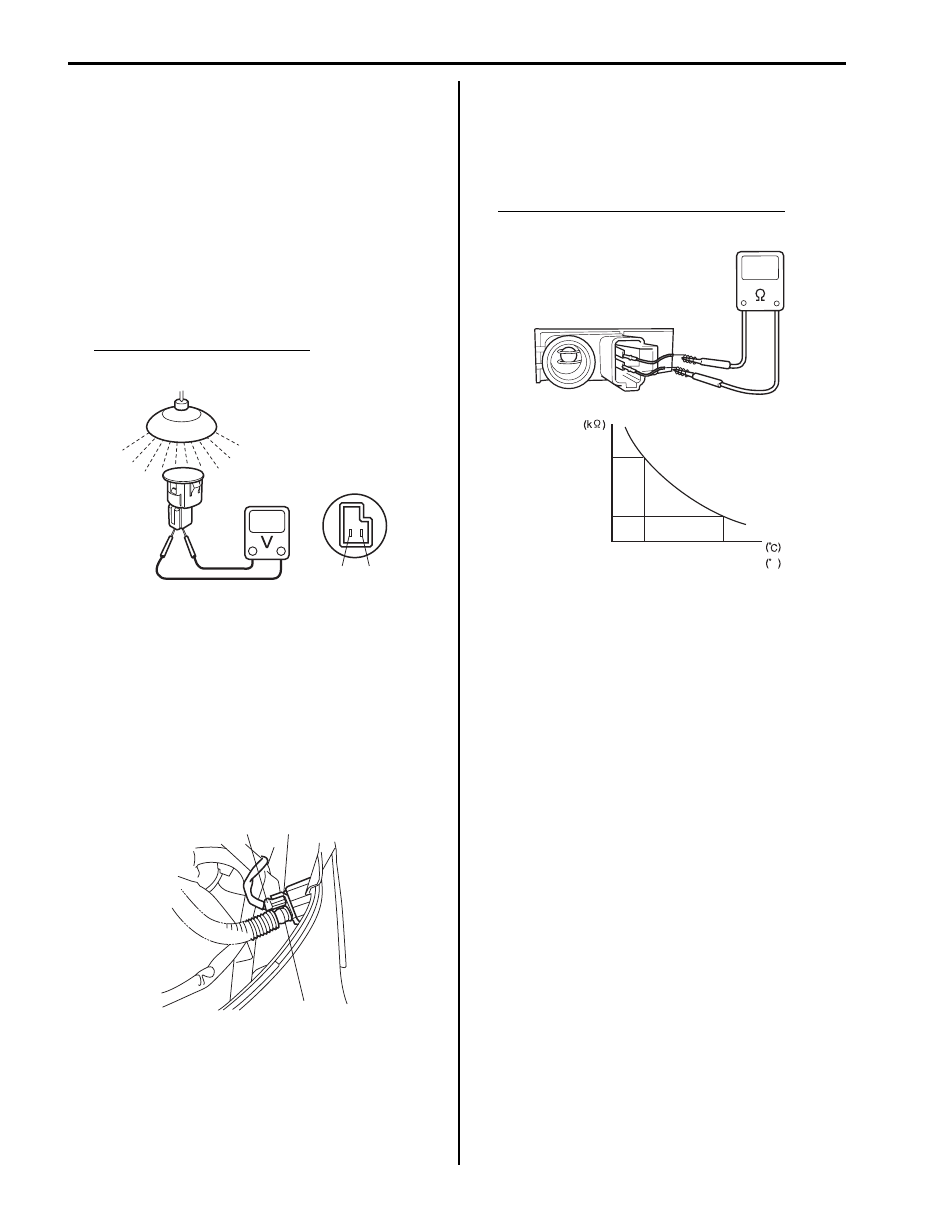
Sunload Sensor Inspection
S5JB0A7206053
1) Remove sunload sensor. Refer to “Sunload Sensor
2) Light over the sensor vertically with an incandescent
lamp of approximately 100 watt.
3) The distance between the sensor and the lamp
should be approximately 100 mm (3.94 in.).
4) Measure the voltage between the terminals with the
(+) probe on the terminal “a” and the (–) probe on the
terminal “b”.
5) Make sure if the voltage is approximately 0.38 – 0.42
V. If not, replace the sensor with the new one.
Sunload sensor specifications
“a” – “b”: Approx. 0.38 – 0.42 V
Inside Air Temperature Sensor Removal and
Installation
S5JB0A7206054
Removal
1) Disconnect negative cable (–) at battery.
2) Remove steering column hole cover.
3) Disconnect inside air temperature sensor connector
(1) and aspirator hose (2).
4) Remove inside air temperature sensor (3) from
vehicle.
Installation
Reverse removal procedure.
Inside Air Temperature Sensor Inspection
S5JB0A7206055
1) Remove Inside air temperature sensor referring to
“Inside Air Temperature Sensor Removal and
Installation”.
2) Check resistance between terminals.
Inside air temperature sensor resistance
Approx. 1.7 k
Ω ± 85 Ω at 25 °C (77 °F)
Outside Air Temperature Sensor Removal and
Installation
S5JB0A7206056
Refer to “Outside Air Temperature Sensor Removal and
Installation (If Equipped) in Section 9C”.
Outside Air Temperature Sensor Inspection
S5JB0A7206057
Refer to “Outside Air Temperature Sensor Inspection (If
Equipped) in Section 9C”.
Air Flow Control Actuator Removal and
Installation
S5JB0A7206058
Refer to “Air Flow Control Actuator Removal and
Installation in Section 7A”.
Air Flow Control Actuator Inspection
S5JB0A7206059
Refer to “Air Flow Control Actuator Inspection in Section
7A”.
“b”
“a”
I5JB0A720053-01
2
3
1
I5JB0A720054-01
Temperature
Resistance
1.7
0
32
25
77
F
5.5
I5JB0A720055-01
Air Conditioning System: 7B-74
Air Intake Control Actuator Removal and
Installation
S5JB0A7206060
Refer to “Air Intake Control Actuator Removal and
Installation in Section 7A”.
Air Intake Control Actuator Inspection
S5JB0A7206061
Refer to “Air Intake Control Actuator Inspection in
Section 7A”.
Temperature Control Actuator Removal and
Installation
S5JB0A7206062
Refer to “Temperature Control Actuator Removal and
Installation in Section 7A”.
Temperature Control Actuator Inspection
S5JB0A7206063
Refer to “Temperature Control Actuator Inspection in
Section 7A”.
HVAC Control Module Removal and Installation
S5JB0A7206023
Refer to “HVAC Control Module Removal and Installation
in Section 7A”.
A/C Compressor Drive Belt Inspection and
Adjustment
S5JB0A7206039
For M16 engine model referring to “P/S Pump and A/C
Compressor (If Equipped) Drive Belt Inspection and
Adjustment for M16 Engine Model in Section 6C”.
For J20 engine model referring to “Water Pump and
Generator Drive Belt On-Vehicle Inspection (For J20
Engine) in Section 1J”.
A/C Compressor Drive Belt Removal and
Installation
S5JB0A7206064
For M16 engine model referring to “P/S Pump and A/C
Compressor (If Equipped) Drive Belt Removal and
Installation for M16 Engine Model in Section 6C”.
For J20 engine model referring to “Water Pump and
Generator Drive Belt Removal and Installation (For J20
Engine) in Section 1J”.
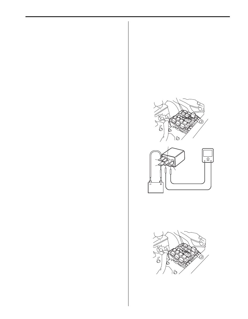
A/C Compressor Relay Inspection
S5JB0A7206040
For M16 Engine Model
1) Disconnect negative (–) cable at battery.
2) Remove compressor relay (1) from vehicle.
3) Check that there is no continuity between terminal
“c” and “d”. If there is continuity, replace relay.
4) Connect battery positive (+) terminal to terminal “b”
of relay.
Connect battery negative (–) terminal to terminal “a”
of relay.
Check continuity between terminal “c” and “d”.
If there is no continuity when relay is connected to
the battery, replace relay.
For J20 Engine Model
1) Disconnect negative cable at battery.
2) Remove included in integration relay No.2 (1) from
vehicle.
1
a
b
c
d
I5JB0A720056-01
1
I5JB0A720057-01
Нет комментариевНе стесняйтесь поделиться с нами вашим ценным мнением.
Текст