Suzuki Grand Vitara JB416 / JB420. Manual — part 294
7B-67 Air Conditioning System:
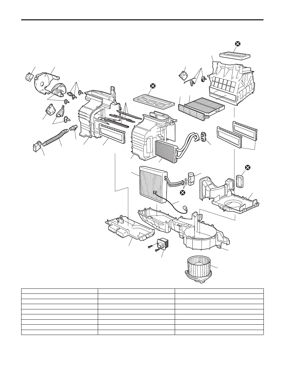
HVAC Unit Components
S5JB0A7206011
20
19
21
25
16
17
22
22
18
3
2
1
5
23
24
16
15
26
26
26
27
26
4
6
14
1
7
9
13
12
10
8
11
I6JB01720012-01
1. Blower upper case
10. Blower lower case
19. Temperature control links
2. Air intake control actuator
11. Blower motor
20. Temperature control actuator
3. Air intake control links
12. Blower motor controller
21. Inside air temperature sensor
4. Air filter (if equipped)
13. Foot duct
22. Air flow control links
5. Air filter cover
14. Aspirator
23. Air flow control links cover
6. Air intake control door assembly
15. Heater core
24. Air flow control actuator
7. Expansion valve
16. Heater unit upper case
25. Aspirator hose
8. Evaporator
17. Temperature control door assembly
26. Packing
9. Evaporator temperature sensor
18. Air flow control door assembly
27. O-ring
Air Conditioning System: 7B-68
CAUTION
!
Be careful not to damage A/C evaporator fins. If A/C evaporator fin is bent, straighten it by using flat
head screwdriver or pair of pliers.
HVAC Unit Removal and Installation
S5JB0A7206012
Removal
WARNING
!
Failure to follow the following procedure and
WARNING may cause air bag deployment,
personal injury, damage to parts, or air bag
being unable to deploy.
• Never rest a steering column assembly on
steering wheel with air bag (inflator)
module face down and column vertical.
• When handling the air bag (inflator)
modules (driver and passenger), be careful
not to drop it or apply an impact to it. If an
excessive impact was applied (e.g.,
dropped from a height of 91.4 cm (3 feet) or
more, never attempt disassembly or repair
but replace it with a new one.
• When grease, cleaning agent. Oil, water,
etc. has got onto air bag (inflator) modules
(driver and passenger), wipe off
immediately with a dry cloth.
1) Disconnect negative (–) cable at battery.
2) Disable air bag system referring to “Disabling Air
3) Recover refrigerant from A/C system using recovery
and recycling equipment referring to “Recovery” in
“Operation Procedure for Charging A/C with
Refrigerant”.
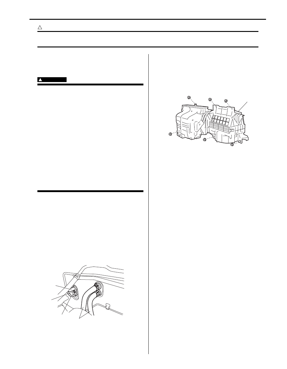
4) Drain engine coolant and disconnect heater hoses
(1) from HVAC unit.
5) Disconnect suction hose (2) and condenser outlet
hose (3) by removing attaching bolt (4).
6) Remove instrument panel referring to “Instrument
Panel Removal and Installation in Section 9C”.
7) Disconnect rear duct from HVAC unit.
8) Detach wiring, connectors and clamps from HVAC
unit.
9) Remove HVAC unit (1).
Installation
1) Install HVAC unit by reversing removal procedure,
noting the following items.
• When installing each part, be careful not to catch
any wiring harness.
• Replenish specified amount of compressor oil to
compressor suction side referring to “Precautions
on Replenishing Compressor Oil”.
• Install the padding (1) to the installation hole
uniformly.
• Fill engine coolant to radiator.
• Enable air bag system referring to “Enabling Air
• Evacuate and charge system. Refer to “Operation
Procedure for Charging A/C with Refrigerant”.
1
3
2
4
I5JB0A720043-01
1
I5JB0A720044-01
7B-69 Air Conditioning System:
A/C Evaporator Removal and Installation
S5JB0A7206013
Removal
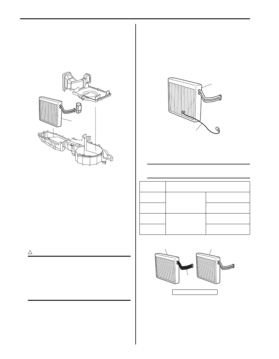
1) Remove HVAC unit referring to “HVAC Unit Removal
2) Remove evaporator (1) from HVAC unit by
disassembling HVAC unit.
3) Remove evaporator temperature sensor from
evaporator.
Installation
Reverse removal procedure to install A/C evaporator
nothing the following instructions.
• Install evaporator temperature sensor onto evaporator
referring to “A/C Evaporator Temperature Sensor
Removal and Installation”.
A/C Evaporator Inspection
S5JB0A7206014
1) Check evaporator fins for blockage. If found clogged,
use compressed air to clean the fins.
CAUTION
!
• Do not use water for cleaning of
evaporator.
• Be careful not to damage evaporator fins.
If evaporator fin is bent, straighten it by
using a screwdriver or pair of pliers. If any
leakage is found from fitting or tube, repair
or replace evaporator.
2) Check inlet and outlet fittings for crack or scratch.
Repair them as required.
A/C Evaporator Temperature Sensor Removal
and Installation
S5JB0A7206015
Removal
1) Remove A/C evaporator (1) referring to “A/C
Evaporator Removal and Installation”.
2) Remove A/C evaporator temperature sensor (2)
from evaporator.
Installation
1) Identify evaporator by the following tables.
NOTE
As for Evaporator, there are 4 varieties
depending on the internal structure.
1
I5JB0A720045-02
Evaporator
type
Selection condition
A
LH steering vehicle
Evaporator with
protection rubber (1)
B
Evaporator without
protection rubber (2)
C
RH steering vehicle
Evaporator with
protection rubber
D
Evaporator without
protection rubber
3. Protection rubber
1
2
I5JB0A720046-01
1
2
3
I5GEB4720001-01
Air Conditioning System: 7B-70
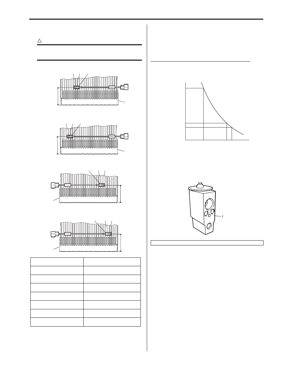
2) Install evaporator temperature sensor onto
evaporator in a correct position as shown in figure.
CAUTION
!
Mis-position causes insufficiency cooling
and damaged of A/C system.
A/C Evaporator Temperature Sensor Inspection
S5JB0A7206016
Check resistance between A/C evaporator temperature
sensor terminals. If check result is not in specification,
replace A/C evaporator temperature sensor with the new
one.
A/C evaporator temperature sensor resistance
11.2 – 11.5 k
Ω at 0 °C (32 °F)
3.8 – 3.9 k
Ω at 25 °C (77 °F)
Expansion Valve On-Vehicle Inspection
S5JB0A7206018
Refer to “A/C System Performance Inspection”.
[A]: Evaporator type A
5. Holding part fixed to fin of 6th
line from the left-side edge
[B]: Evaporator type B
6. Sensor part fixed to fin of 5th
line from the left-side edge
[C]: Evaporator type C
7. Holding part fixed to fin of 3rd
line from the left-side edge
[D]: Evaporator type D
8. Sensor part fixed to fin of 8th
line from the right-side edge
1. Evaporator temperature
sensor
9. Holding part fixed to fin of 6th
line from the right-side edge
2. Evaporator
10. Sensor part fixed to fin of 5th
line from the right-side edge
3. 34.5 mm (1.36 in.)
11. Holding part fixed to fin of 3rd
line from the right-side edge
4. Sensor part fixed to fin of 8th
line from the left-side edge
4
2
5
6
7
9
8
11
10
3
[A]
[B]
2
3
2
3
[C]
[D]
2
3
1
1
1
1
I5GEB4720002-03
1. Expansion valve
(k
Ω
)
11.4
3.9
3.3
0
32
25
77
30
86
(˚C)
(˚F)
Resistance
Temperature
I5JB0A720090-03
IYSQ01720049-01
Нет комментариевНе стесняйтесь поделиться с нами вашим ценным мнением.
Текст