Suzuki Grand Vitara JB416 / JB420. Manual — part 44
1A-125 Engine General Information and Diagnosis:
Step
Action
Yes
No
1
Was “Engine and Emission Control System Check”
performed?
Go to Step 2.
Go to “Engine and
Emission Control
System Check”.
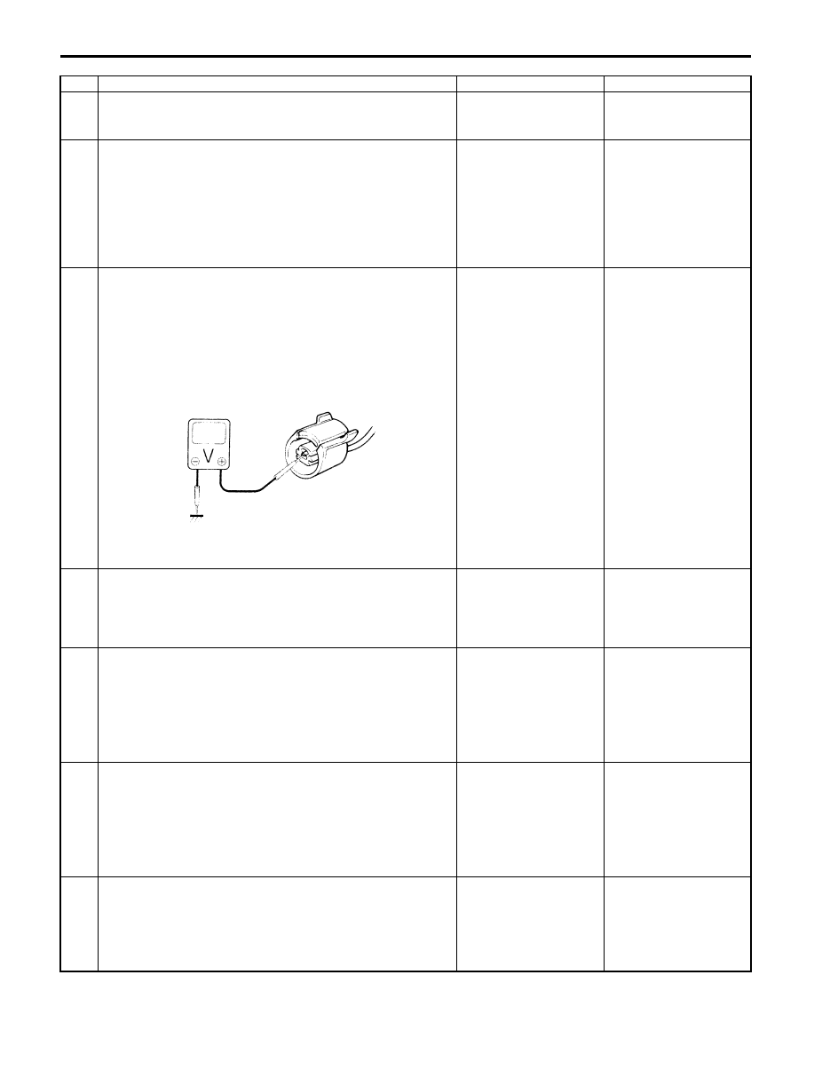
2
Knock sensor circuit check
1) Remove ECM from its bracket with ECM connectors
connected.
2) Measure voltage between “C37-56” terminal of ECM
connector and vehicle body ground with engine running.
Is voltage within 1.23 – 3.91 V?
Intermittent trouble.
Check for intermittent
referring to “Intermittent
and Poor Connection
Inspection in Section
00”. If OK, substitute a
known-good ECM and
recheck.
Go to Step 3.
3
Knock sensor circuit for open check
1) Disconnect connector from knock sensor with ignition
switch turned OFF.
2) Turn ON ignition switch, measure voltage between
“WHT” wire of knock sensor connector and engine
ground.
Is voltage 4 – 6 V?
Go to Step 6.
Go to Step 4.
4
Knock sensor circuit for open check
1) Turn ON ignition switch, measure voltage between “C37-
56” terminal of ECM connector and engine ground
Is voltage 4 – 6 V?
“WHT” wire is open
circuit.
Go to Step 5.
5
Knock sensor circuit for short check
1) Disconnect connectors from ECM with ignition switch
turned OFF.
2) Measure resistance between “C37-56” terminal of ECM
connector and vehicle body ground.
Is resistance infinity?
Go to Step 6.
“WHT” wire is shorted to
ground circuit.
If wire is OK, substitute
a known-good ECM and
recheck.
6
Knock sensor circuit for short check
1) Disconnect connectors from ECM with ignition switch
turned OFF.
2) Turn ON ignition switch, measure voltage between “C37-
56” terminal of ECM connector and vehicle body ground.
Is voltage 0 V?
Go to Step 7.
“WHT” wire is shorted to
other circuit.
7
Knock sensor circuit for high resistance check
1) Turn OFF ignition switch, measure resistance between
“C37-56” terminal of ECM connector and “RED” wire
terminal of knock sensor harness connector.
Is resistance below 5
Ω
?
Faulty knock sensor.
“WHT” wire is high
resistance circuit.
I2RH01110089-01
Engine General Information and Diagnosis: 1A-126
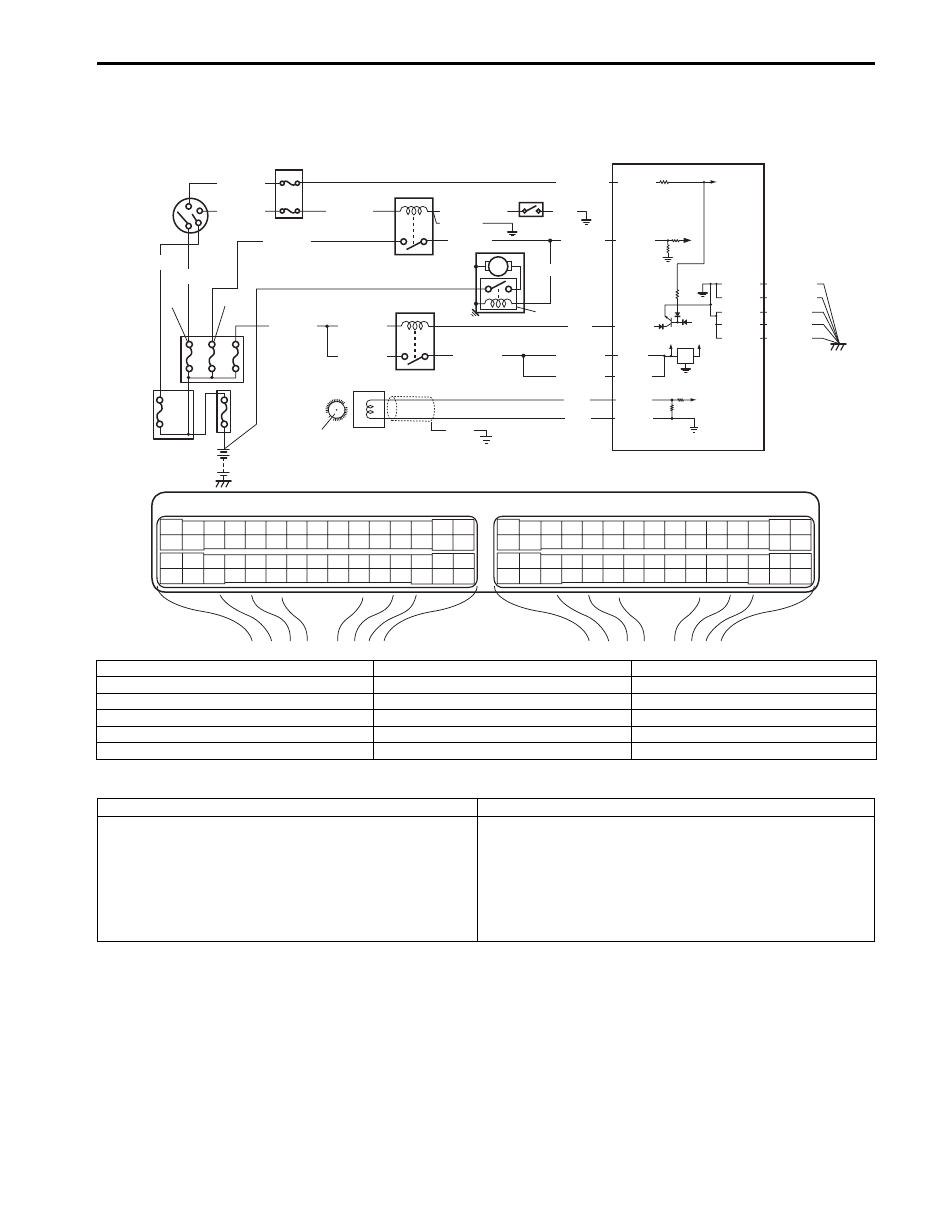
DTC P0335: Crankshaft Position (CKP) Sensor Circuit (For J20 Engine)
S5JB0A1104089
Wiring Diagram
DTC Detecting Condition and Trouble Area
DTC Confirmation Procedure
1) With ignition switch turned OFF, connect scan tool.
2) Turn ON ignition switch and clear DTC using scan tool.
3) Crank engine for 3 – 5 sec.
4) Check DTC and pending DTC.
E23
C37
3
4
18
19
5
6
7
10
11
17
20
47
46
49
50
51
21
22
52
16
25
9
24
14
29
55
57
54 53
59
60
58
2
26
27
28
15
30
56
48
32
31
34
35
36
37
40
42
39 38
44
45
43
41
33
1
12
13
23
8
3
4
18
19
5
6
7
10
11
17
20
47
46
49
50
51
21
22
52
16
25
9
24
14
29
55
57
54 53
59
60
58
2
26
27
28
15
30
56
48
32
31
34
35
36
37
40
42
39 38
44
45
43
41
33
1
12
13
23
8
12V
5V
BLU/BLK
BLU/BLK
BLK/RED
BLK/RED
BLK/RED
BLU
5
4
13
3
E23-29
E23-1
E23-60
E23-16
7
BLK/YEL
BLK/YEL
BLK/YEL
C37-22
BLK/WHT
BLK/YEL
BLK/YEL
BLK/YEL
[A]: BLK/RED
[B]: BLK
6
12
11
14
WHT/GRN
WHT/RED
8
BLK/RED
10
BLK
BLU/BLK
9
C37-15
C37-29
C37-48
BLK/ORN
C37-58
C37-30 BLK/ORN
BLK/YEL
BLK/YEL
BLK/YEL
BLU
PNK
C37-36
C37-51
BLK
1
2
15
I5JB0A110047-02
[A]: For A/T model
5. Ignition switch
11. “ST” fuse
[B]: For M/T model
6. Starting motor
12. “ST SIG” fuse
1. CKP sensor
7. Starting motor control relay
13. “IG COIL” fuse
2. Sensor plate on crankshaft
8. Transmission range switch (for A/T model)
14. “IGN” fuse
3. ECM
9. Fuse box No.2
15. Starting motor magnet clutch
4. Main relay
10. “FI” fuse
DTC detecting condition
Trouble area
No CKP sensor signal for 2 sec. even if starting motor
signal is inputted at engine cranking.
(1 driving cycle detection logic)
• CKP sensor circuit open or short
• Sensor plate teeth damaged
• CKP sensor malfunction, foreign material being attached
or improper installation
• ECM
• Engine start signal circuit malfunction

1A-127 Engine General Information and Diagnosis:
DTC Troubleshooting
NOTE
Before this trouble shooting is performed, read the precautions for DTC troubleshooting referring to
“Precautions For DTC Troubleshooting”.
Step
Action
Yes
No
1
Was “Engine and Emission Control System Check”
performed?
Go to Step 2.
Go to “Engine and
Emission Control
System Check”.
2
CKP sensor and connector for proper installation check
Is CKP sensor installed properly and connector connected
securely?
Go to Step 3.
Correct.
3
Wire circuit check
1) Disconnect connector from CKP sensor with ignition
switch turned OFF.
2) Check for proper connection to CKP sensor at “PNK”
and “BLU” wire terminals.
3) If OK, measure voltage between engine ground and
each “PNK” and “BLU” wire terminals of CKP sensor
connector with ignition switch turned ON.
Is each voltage 0 V?
Go to Step 4.
“PNK” wire and/or “BLU”
wire is shorted to other
circuit.
4
Wire circuit check
1) Disconnect connectors from ECM with ignition switch
turned OFF.
2) Check for proper connection to ECM at “C37-36” and
“C37-51” terminals.
3) If OK, measure resistance between engine ground and
each “C37-36” and “C37-51” terminals of ECM
connector.
Is each resistance infinity?
Go to Step 5.
“PNK” wire and/or “BLU”
wire is shorted to
ground circuit.
5
Wire circuit check
1) Measure resistance at following connector terminals.
• Between “C37-51” terminal of ECM connector and
“BLU” wire terminal of CKP sensor connector
• Between “C37-36” terminal of ECM connector and
“PNK” wire terminal of CKP sensor connector
Is each resistance below 5
Ω
?
Go to Step 6.
“PNK” wire and/or “BLU”
wire is open or high
resistance.
6
Engine start signal check
1) Check starting motor circuit for opening and short
referring to Step 2 of “DTC P0616: Starter Relay Circuit
Low” and Step 3 and 4 of “DTC P0617: Starter Relay
Circuit High”.
Is check result satisfactory?
Go to Step 7.
Repair or replace.
7
CKP sensor check
1) Check CKP sensor and sensor plate tooth referring to
“Camshaft Position (CMP) Sensor Inspection in Section
1C”.
Is check result satisfactory?
Substitute a known-
good ECM and recheck.
Replace CKP sensor
and/or sensor plate.
Engine General Information and Diagnosis: 1A-128
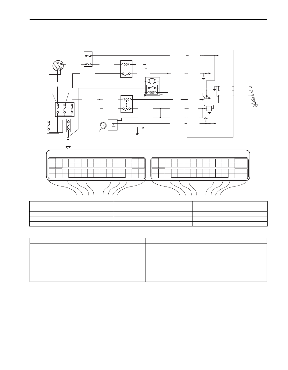
DTC P0335: Crankshaft Position (CKP) Sensor Circuit (For M16 Engine)
S5JB0A1104040
Wiring Diagram
DTC Detecting Condition and Trouble Area
E23
C37
3
4
18
19
5
6
7
10
11
17
20
47
46
49
50
51
21
22
52
16
25
9
24
14
29
55
57
54 53
59
60
58
2
26
27
28
15
30
56
48
32
31
34
35
36
37
40
42
39 38
44
45
43
41
33
1
12
13
23
8
3
4
18
19
5
6
7
10
11
17
20
47
46
49
50
51
21
22
52
16
25
9
24
14
29
55
57
54 53
59
60
58
2
26
27
28
15
30
56
48
32
31
34
35
36
37
40
42
39 38
44
45
43
41
33
1
12
13
23
8
12V
5V
BLK/RED
BLK/RED
BLK/RED
BLU
5
4
13
3
E23-29
E23-60
7
BLK/YEL
BLK/YEL
BLK/YEL
C37-22
BLK/WHT
BLK/YEL
BLK/YEL
BLK/YEL
6
12
11
14
WHT/GRN
WHT/RED
BLK/RED
10
E23-1
BLK
9
C37-15
C37-29
C37-48
BLK/ORN
C37-58
C37-30 BLK/ORN
BLK/YEL
BLK/YEL
BLK/YEL
15
BLU/BLK
E23-16
1
C37-51
5V
2
BLK/YEL
WHT/BLU
BLU/BLK
BLU/BLK
BLU/BLK
8
I5JB0A110048-02
1. CKP sensor
6. Starting motor
11. “ST” fuse
2. Sensor plate on crankshaft
7. Starting motor control relay
12. “ST SIG” fuse
3. ECM
8. To CMP sensor
13. “IG COIL” fuse
4. Main relay
9. Fuse box No.2
14. “IGN” fuse
5. Ignition switch
10. “FI” fuse
15. Starting motor magnet clutch
DTC detecting condition
Trouble area
No CKP sensor signal for 2 sec. even if starting motor
signal is inputted at engine cranking.
(1 driving cycle detection logic)
• CKP sensor circuit open or short
• Sensor plate teeth damaged
• CKP sensor malfunction, foreign material being attached
or improper installation
• ECM
• Engine start signal circuit malfunction
Нет комментариевНе стесняйтесь поделиться с нами вашим ценным мнением.
Текст