Suzuki Grand Vitara JB416 / JB420. Manual — part 45
1A-129 Engine General Information and Diagnosis:
DTC Confirmation Procedure
1) With ignition switch turned OFF, connect scan tool.
2) Turn ON ignition switch and clear DTC using scan tool.
3) Crank engine for 3 – 5 sec.
4) Check DTC and pending DTC.
DTC Troubleshooting
NOTE
Before this trouble shooting is performed, read the precautions for DTC troubleshooting referring to
“Precautions For DTC Troubleshooting”.
Step
Action
Yes
No
1
Was “Engine and Emission Control System Check”
performed?
Go to Step 2.
Go to “Engine and
Emission Control
System Check”.
2
CKP sensor and connector for proper installation check
Is CKP sensor installed properly and connector connected
securely?
Go to Step 3.
Correct.
3
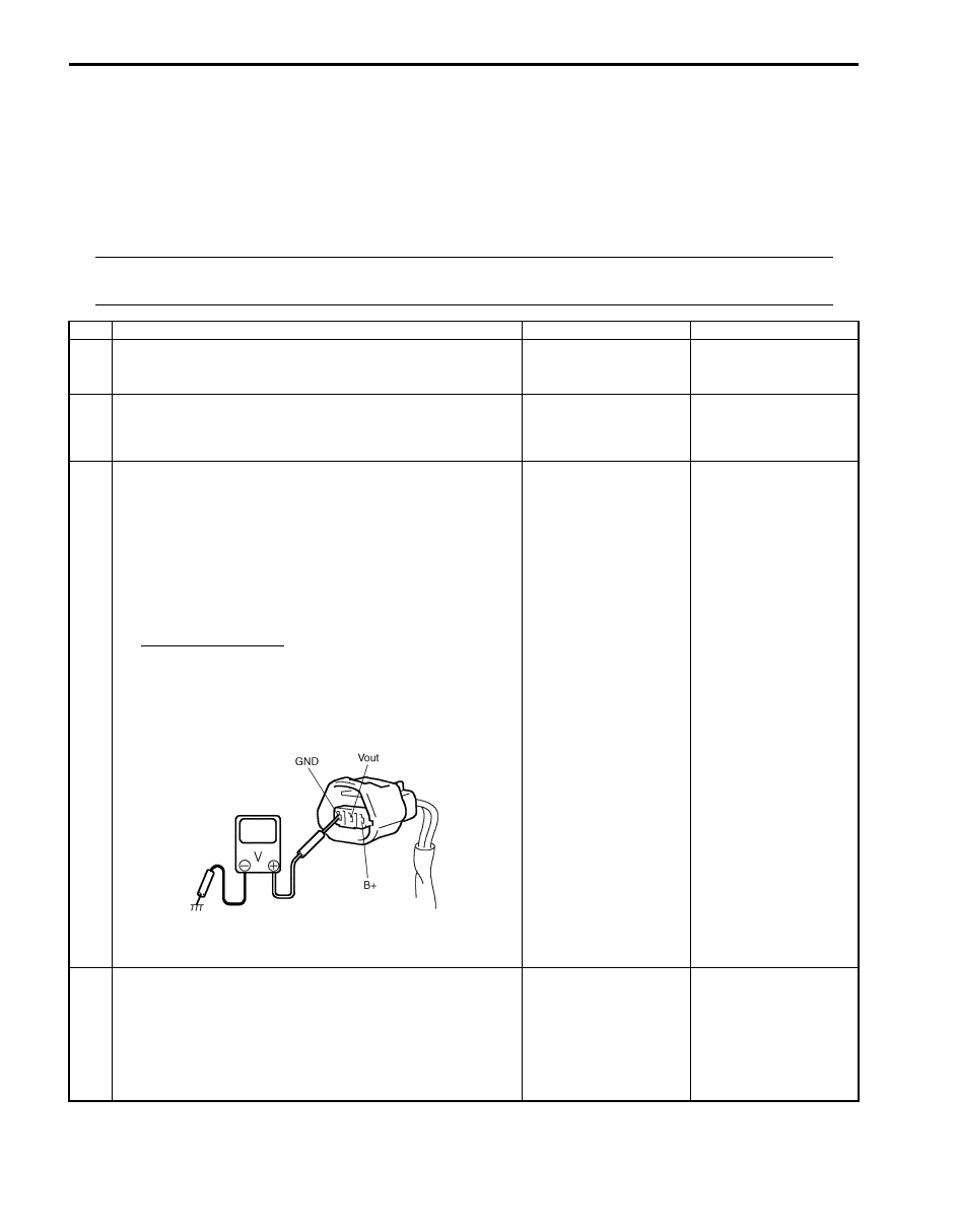
Wire harness and connection check
1) Disconnect connector from CKP sensor with ignition
switch turned OFF.
2) Check for proper connection to CKP sensor at “BLU/
BLK”, “WHT/BLU” and “BLK/YEL” wire terminals.
3) If OK, turn ON ignition switch and check voltage at “BLU/
BLK”, “WHT/BLU” and “BLK/YEL” wire terminals of
disconnected CKP sensor connector.
CKP sensor voltage
Terminal “B+”: 10 – 14 V
Terminal “Vout”: 4 – 5 V
Terminal “GND”: 0 V
Is check result satisfactory?
Go to Step 7.
Go to Step 4.
4
Was terminal “Vout” voltage in Step 3 within specification?
Go to Step 5.
“WHT/BLU” wire is open
or shorted to ground /
power supply circuit.
If wire and connection
are OK, substitute a
known-good ECM and
recheck.
I2RH0B110048-01

Engine General Information and Diagnosis: 1A-130
5
Ground circuit check
1) Turn ignition switch to OFF position.
2) Measure resistance between “BLK/YEL” wire terminal of
CKP sensor connector and engine ground.
Is measured resistance value less than 3
Ω
?
Go to Step 6.
“BLK/YEL” wire is open
or high resistance.
6
Was terminal “B+” voltage in Step 3 within specification?
Go to Step 7.
“BLU/BLK” wire is open
circuit. If wire and
connection are OK,
substitute a known-
good ECM and recheck.
7
Engine start signal check
1) Check starting motor circuit for opening and short
referring to Step 2 of “DTC P0616: Starter Relay Circuit
Low” and Step 3 and 4 of “DTC P0617: Starter Relay
Circuit High”.
Is check result satisfactory?
Go to Step 8.
Repair or replace.
8
CKP sensor check
1) Check CKP sensor and sensor plate tooth referring to
“Camshaft Position (CMP) Sensor Inspection in Section
1C”.
Is check result satisfactory?
Substitute a known-
good ECM and recheck.
Replace CKP sensor
and/or sensor plate.
Step
Action
Yes
No
1A-131 Engine General Information and Diagnosis:
DTC P0340: Camshaft Position (CMP) Sensor Circuit
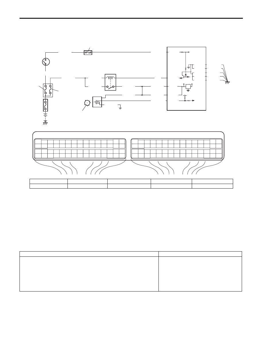
S5JB0A1104041
Wiring Diagram
System Description
The CMP sensor located on the transmission side of cylinder head (for M16 engine) or cylinder head cover (for J20
engine) consists of the signal generator (magnetic sensor) and signal rotor (intake camshaft portion).
The signal generator generates reference signal through slits in the slit plate which turns together with the camshaft.
Reference signal
The CMP sensor generates 6 pulses of signals each of which has a different waveform length while the camshaft
makes one full rotation. Refer to “Inspection of ECM and Its Circuits”.
Based on these signals, ECM judges which cylinder piston is in the compression stroke and the engine speed.
DTC Detecting Condition and Trouble Area
DTC Confirmation Procedure
1) With ignition switch turned OFF, connect scan tool.
2) Turn ON ignition switch and clear DTC using scan tool.
3) Crank engine for 5 sec.
4) Check DTC and pending DTC.
E23
C37
3
4
18
19
5
6
7
10
11
17
20
47
46
49
50
51
21
22
52
16
25
9
24
14
29
55
57
54 53
59
60
58
2
26
27
28
15
30
56
48
32
31
34
35
36
37
40
42
39 38
44
45
43
41
33
1
12
13
23
8
3
4
18
19
5
6
7
10
11
17
20
47
46
49
50
51
21
22
52
16
25
9
24
14
29
55
57
54 53
59
60
58
2
26
27
28
15
30
56
48
32
31
34
35
36
37
40
42
39 38
44
45
43
41
33
1
12
13
23
8
12V
5V
BLU/BLK
BLU/BLK
BLK/RED
BLK/RED
BLK/RED
BLU
5
6
4
8
3
E23-29
E23-1
E23-60
7
E23-16
1
C37-52
5V
BLK/YEL
BLK/WHT
9
WHT/GRN
2
WHT/RED
BLU/BLK
BLU/BLK
BLK/YEL
C37-15
C37-29
C37-48
BLK/ORN
C37-58
C37-30 BLK/ORN
BLK/YEL
BLK/YEL
BLK/YEL
I5JB0A110049-01
1. CMP sensor
3. ECM
5. Ignition switch
7. “FI” fuse
9. “IGN” fuse
2. Signal rotor
4. Main relay
6. Fuse box No.2
8. “IG COIL” fuse
DTC detecting condition
Trouble area
• CMP sensor pulse is less than 20 pulses per crankshaft 8 revolutions
• CMP sensor pulse is more than 28 pulses per crankshaft 8 revolutions
• CMP sensor pulse is less than 20 pulses between BTDC 155
° crank
angle (for M16 engine) or BTDC 75
° crank angle (for J20 engine) and
BTDC 5
° crank angle with crankshaft 8 revolutions from engine start.
(1 driving cycle detection logic)
• CMP sensor circuit open or short
• Signal rotor teeth damaged
• CMP sensor malfunction, foreign
material being attached or improper
installation
• ECM
Engine General Information and Diagnosis: 1A-132
DTC Troubleshooting
NOTE
Before this trouble shooting is performed, read the precautions for DTC troubleshooting referring to
“Precautions For DTC Troubleshooting”.
Step
Action
Yes
No
1
Was “Engine and Emission Control System Check”
performed?
Go to Step 2.
Go to “Engine and
Emission Control
System Check”.
2
CMP sensor and connector for proper installation check
Is CMP sensor installed properly and connector connected
securely?
Go to Step 3.
Correct.
3
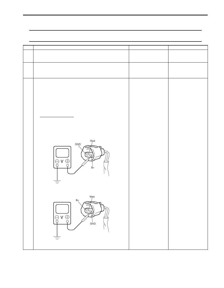
Wire harness and connection check
1) Disconnect connector from CMP sensor.
2) Check for proper connection to CMP sensor at “BLU/
BLK”, “WHT/RED” and “BLK/YEL” wire terminals.
3) If OK, turn ON ignition switch and check voltage at “BLU/
BLK”, “WHT/RED” and “BLK/YEL” wire terminals of
disconnected CMP sensor connector.
CMP sensor voltage
Terminal “B+”: 10 – 14 V
Terminal “Vout”: 4 – 5 V
Terminal “GND”: 0 V
For J20 engine
For M16 engine
Is check result satisfactory?
Go to Step 7.
Go to Step 4.
I5JB0A110050-01
I4RS0B110094-01
Нет комментариевНе стесняйтесь поделиться с нами вашим ценным мнением.
Текст