Suzuki Grand Vitara JB416 / JB420. Manual — part 247
5A-122 Automatic Transmission/Transaxle:
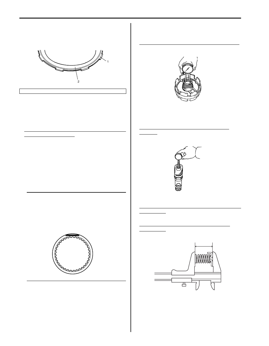
• When installing brake discs, brake plates and clutch
backing plate, refer to “Center Support Components”.
• Install clutch backing plate (1) with its flat side facing
brake disc.
• After installing each retaining backing plate ring,
measure movement of brake piston again.
If it is not within standard range, it is possible that ring
is not installed properly. Then disassemble and
reassemble again.
Standard movement of second coast brake piston
and second brake piston
Second coast brake piston: 1.00 – 1.20 mm (0.039
– 0.047 in.)
Second brake piston: 1.01 – 2.25 mm (0.040 –
0.089 in.)
Center Support Inspection
S5JB0A5106089
• Check that sliding surface of discs and plate are not
worn or burnt. If necessary, replace them.
NOTE
• If disc lining is exfoliated, discolored or
worn hardly, replace all discs.
• If only a part of printed numbers is
corroded, replace all discs.
• Before assembling new discs, soak them
in A/T fluid for at least 15 minutes.
• Measure inside diameter of center support hub
bushing. If inside diameter exceeds limit, replace
center support.
Center support bushing inside diameter standard
36.386 – 36.411 mm (1.4325 – 1.4335 in.)
• Measure inside diameter of planetary sun gear
bushing. If inside diameter exceeds limit, replace
planetary sun gear.
Planetary sun gear bushing inside diameter
standard
21.501 – 21.527 mm (0.8465 – 0.8475 in.)
• Measure free length of piston return spring.
Standard free length of second coast brake piston
return spring
16.84 mm (0.663 in.)
Standard free length of second brake piston
return spring
15.82 mm (0.623 in.)
2. Step
I5JB0A510122-01
I4JA01512210-01
I5JB0A510123-01
I5JB0A510124-01
I5JB0A510171-01
Automatic Transmission/Transaxle: 5A-123
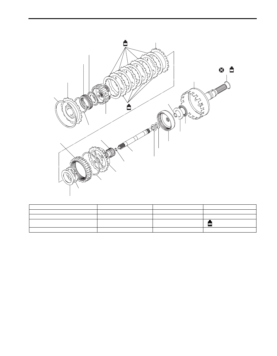
Planetary Gears and Output Shaft Components
S5JB0A5106085
9
4
5
3
2
2
11
10
13
2
12
18
14
16
15
16
14
2
17
1
10
6
18
FLD
8
FLD
7
FLD
I5JB0A510125-02
1. Inner shaft
6. Front planetary gear
11. Front planetary ring gear
16. Bearing race
2. Retaining ring
7. Reverse brake plate
12. Rear planetary gear
17. Output shaft assembly
3. Reverse brake reaction plate
8. Reverse brake disc
13. Planetary sun gear
18. Seal ring
4. One-way clutch
9. Reverse brake backing plate
14. Bearing
: Apply A/T fluid.
5. One-way clutch thrust washer
10. Thrust washer
15. Rear planetary ring gear
5A-124 Automatic Transmission/Transaxle:
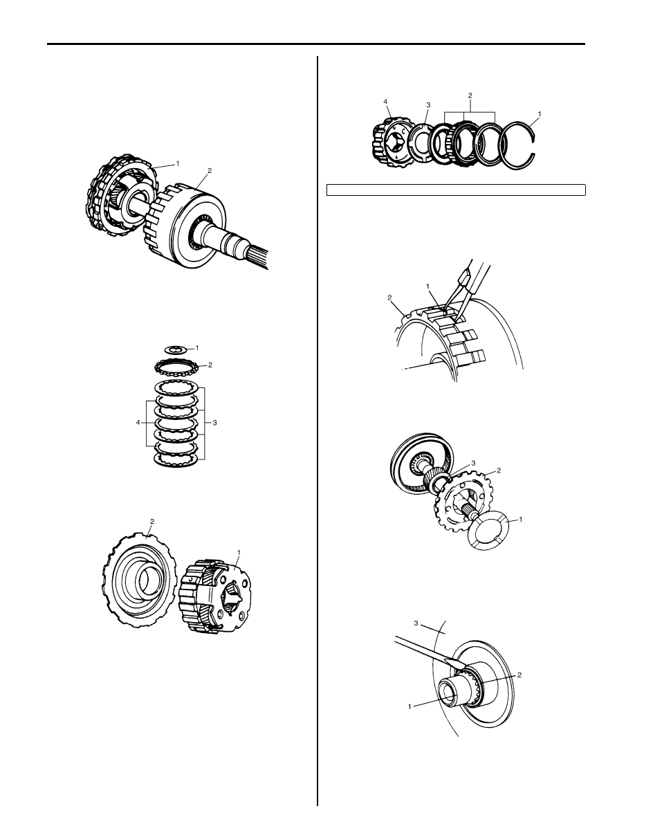
Planetary Gears and Output Shaft Disassembly
and Assembly
S5JB0A5106086
Disassembly
1) Remove front planetary gear assembly (1) from
output shaft assembly (2).
2) Remove rear planetary thrust washer (1), reverse
brake backing plate (2), reverse brake disc (3) and
reverse brake plate (4) from front planetary gear
assembly.
3) Remove reverse brake reaction plate (2) from front
planetary gear (1).
4) After removing retaining ring (1), remove one-way
clutch (2) and one-way clutch rear thrust washer (3).
5) After removing retaining ring (1), remove front
planetary ring gear (2), thrust bearing and bearing
race.
6) Remove thrust washer (1), rear planetary gear (2)
and rear planetary sun gear (3).
7) After removing retaining ring (2) from inner shaft (1),
remove rear planetary ring gear (3) and thrust
bearing assembly.
IYSQ01510185-01
IYSQ01510186-01
IYSQ01510187-01
4. Front planetary gear
IYSQ01510188-01
IYSQ01510189-01
IYSQ01510190-01
IYSQ01510191-01
Automatic Transmission/Transaxle: 5A-125
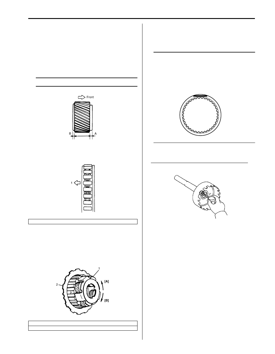
Assembly
Assemble components by reversing disassembly
procedure and noting the following points.
• Refer to “Planetary Gears and Output Shaft
Components” when installing each component.
• Check seal ring for damage before installation and
replace if damaged.
• Install planetary sun gear as shown in the figure.
NOTE
A is longer than B.
• Fit retaining rings into groove securely.
• Install one-way clutch as shown in the figure.
• Install reverse brake reaction plate (2) to front
planetary gear (1).
With reverse brake reaction plate (2) fixed stationary,
turn front planetary gear (1) clockwise to check that it
locks and then counterclockwise to check that it turns
smoothly.
Planetary Gears and Output Shaft Inspection
S5JB0A5106090
• Check that sliding surface of discs and plate are not
worn or burnt. if necessary, replace them.
NOTE
• If disc lining is exfoliated, discolored or
worn hardly, replace all discs.
• If only a part of printed numbers is
corroded, replace all discs.
• Before assembling new discs, soak them
in A/T fluid for at least 15 minutes.
• Measure inside diameter of output shaft bushing. If
inside diameter exceeds limit, replace output shaft.
Output shaft bushing inside diameter standard
18.001 – 18.026 mm (0.7087 – 0.7097 in.)
1. Front planetary gear side
[A]: Rotates
[B]: Locks
I5JB0A510155-01
IYSQ01510193-01
IYSQ01510194-01
I4JA01512210-01
I5JB0A510126-01
Нет комментариевНе стесняйтесь поделиться с нами вашим ценным мнением.
Текст