Suzuki Grand Vitara JB416 / JB420. Manual — part 246

5A-118 Automatic Transmission/Transaxle:
Center Support Components
S5JB0A5106083
1
3
4
5
8
11
4
5
9
15
14
9
9
2
FLD
2
FLD
10
FLD
10
FLD
6
FLD
7
FLD
13
FLD
12
FLD
I5JB0A510116-02
1. Center support
6. Second coast brake plate
11. Second brake piston
: Do not reuse.
2. O-ring
7. Second coast brake disc
12. Second brake plate
: Apply A/T fluid.
3. Second coast brake piston
8. Clutch backing plate
13. Second brake disc
4. Piston return spring
9. Retaining ring
14. Planetary sun gear
5. Snap ring
10. Seal ring
15. Second brake hub assembly
Automatic Transmission/Transaxle: 5A-119
Center Support Disassembly and Assembly
S5JB0A5106084
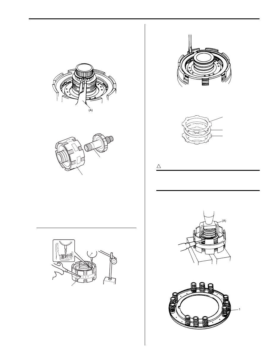
Disassembly
1) Remove retaining ring.
Special tool
(A): 09920–76010
2) Pull out center support assembly (2) from planetary
sun gear (1).
3) Apply compressed air (400 – 800 kPa, 4 – 8 kg/cm
2
,
57 – 113 psi) to oil hole (1) at the extreme left and
measure movement of second coast brake (Second
coast brake) piston.
If measured value is not within standard range,
replace second coast brake plate or second coast
brake disc.
Standard second coast brake piston movement
0.75 – 1.35 mm (0.030 – 0.053 in.)
4) Remove retaining ring.
5) After removing clutch backing plate (1), remove
second coast brake plate (3) and second coast
brake disc (2).
6) Using special tool and hydraulic press, compress
piston return spring and remove snap ring.
CAUTION
!
Be careful when applying pressure, for
overpressure will cause plate section of
piston return spring to deform.
Special tool
(A): 09926–98310
7) Remove brake piston return spring (1).
IYSQ01510165-01
1
2
I5JB0A510117-01
1
I5JB0A510118-01
IYSQ01510168-01
2
3
1
I5JB0A510119-02
IYSQ01510170-01
IYSQ01510171-01
5A-120 Automatic Transmission/Transaxle:
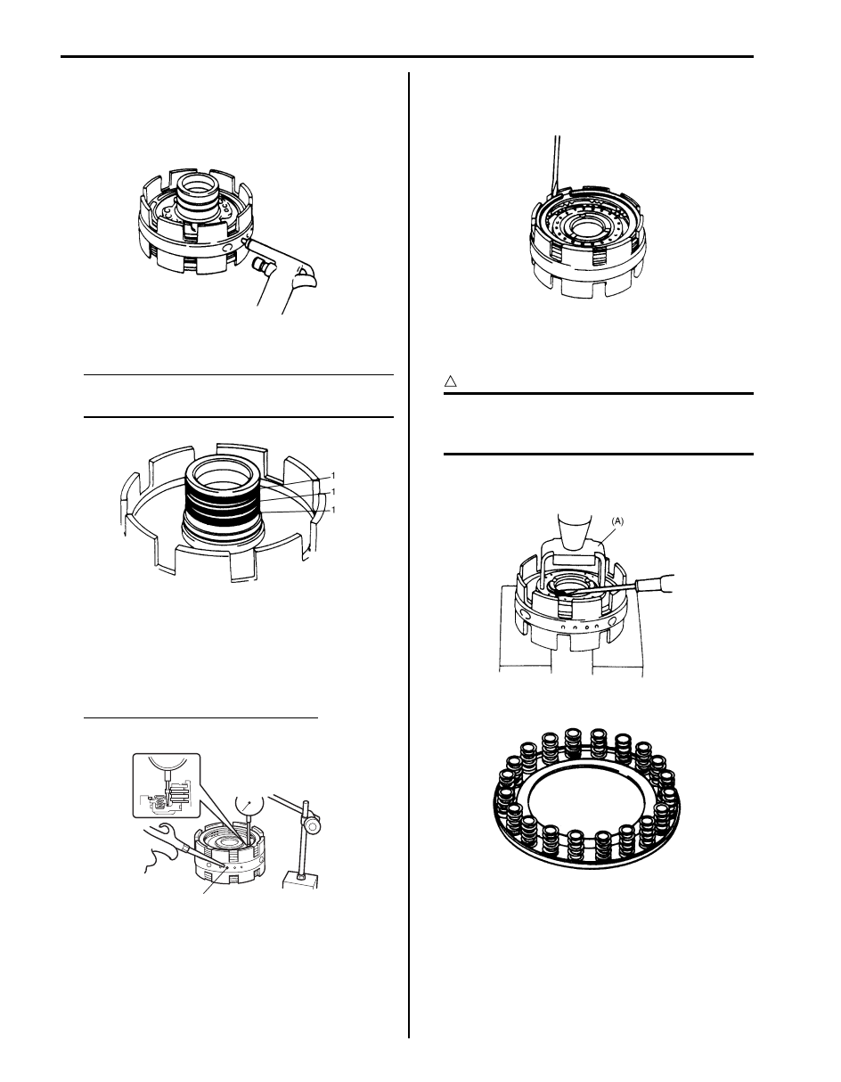
8) Apply compressed air (400 – 800 kPa, 4 – 8 kg/cm
2
,
57 – 113 psi) to oil hole at the extreme left and
remove second coast brake piston as shown in the
figure. Then remove piston inner O-ring and piston
outer O-ring from second coast brake piston.
9) Remove 3 seal rear rings (1).
NOTE
Use care not to open ring more than
necessary.
10) Apply compressed air (400 – 800 kPa, 4 – 8 kg/cm
2
,
57 – 113 psi) to second hole (1) from the left and
measure stroke of second brake (Second brake)
piston as shown in the figure.
If measured value is not within standard range,
replace second brake plate or second brake disc.
Standard second brake piston stroke
0.97 – 1.70 mm (0.038 – 0.067 in.)
11) After removing retaining back plate ring, remove
clutch backing plate, second brake plates and
second brake discs.
12) Using special tool and hydraulic press, compress
brake piston return spring and remove snap second
coast brake ring.
CAUTION
!
Be careful when applying pressure, for
overpressure will cause plate section of
piston return spring to deform.
Special tool
(A): 09926–98310
13) Remove brake piston return spring.
IYSQ01510172-01
IYSQ01510173-01
1
I5JB0A510120-01
IYSQ01510175-01
IYSQ01510176-01
IYSQ01510177-01

Automatic Transmission/Transaxle: 5A-121
14) Blow air into the second air hole from the left and
remove second brake piston. Then remove piston
inner O-ring and piston outer O-ring from second
brake piston.
15) With second brake hub assembly (3) held stationary,
turn planetary sun gear (4) clockwise to check that it
locks and then counterclockwise to check that it
turns smoothly.
16) Remove second brake hub assembly (1) from
planetary sun gear (2).
17) Remove 2 sun gear seal rings (1) from planetary sun
gear.
NOTE
Use care not to open sun gear seal ring more
than necessary.
Assembly
Assemble components by reversing disassembly
procedure and noting the following points.
• Snap both ends of sun gear seal ring (1) securely.
• Do not open sun gear seal ring more than necessary.
• Always use new O-ring and apply A/T fluid before
installation.
• When installing O-ring, make sure that it is not kinked
or caught.
• Push in brake piston horizontally.
• When installing brake piston return spring, be careful
so that spring will not fall or tilt.
• When installing snap ring, do not align lug (1) of
retainer with opening in snap ring (2).
[A]: Locks
[B]: Turns
IYSQ01510178-01
IYSQ01510179-01
IYSQ01510180-01
IYSQ01510181-01
I5JB0A510121-01
IYSQ01510182-01
Нет комментариевНе стесняйтесь поделиться с нами вашим ценным мнением.
Текст