Suzuki Grand Vitara JB416 / JB420. Manual — part 91
1D-32 Engine Mechanical: For M16A Engine with VVT
Wear of Tappet and Shim
Check tappet and shim for pitting, scratches, or damage.
If any malcondition is found, replace.
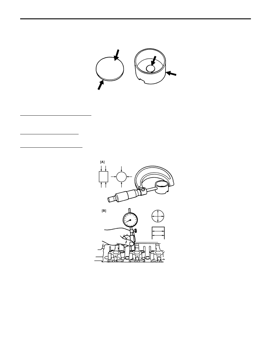
Measure cylinder head bore and tappet outside diameter to determine cylinder head-to-tappet clearance. If clearance
exceeds limit, replace tappet or cylinder head.
Cylinder head to tappet clearance
Standard: 0.025 – 0.066 mm (0.0010 – 0.026 in.)
Limit: 0.15 mm (0.0059 in.)
Tappet outside diameter [A]
Standard: 30.959 – 30.975 mm (1.2189 – 1.2195 in.)
Cylinder head tappet bore [B]
Standard: 31.000 – 31.025 mm (1.2205 – 1.2215 in.)
I2RH0B140085-01
I2RH0B140086-01
Engine Mechanical: For M16A Engine with VVT 1D-33
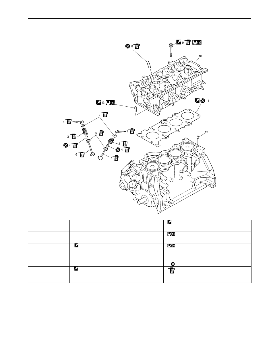
Valves and Cylinder Head Components
S5JB0A1416023
I4RS0A140015-01
1. Valve cotters
7. Exhaust valve
13. Cylinder head bolt (M8)
: Be sure to tighten cylinder head bolt (M8) after
securing the other cylinder head bolt (M10).
2. Valve spring retainer
8. Valve guide
: Tighten 20 N
⋅m (2.0 kgf-m, 14.5 lb-ft), 40 N⋅m (4.0
kgf-m, 29.0 lb-ft), 60
° and 60° by the specified
procedure.
3. Valve spring
9. Cylinder head bolt (M10)
: Check cylinder head bolt (M10), plastic deformation
tightening bolt, for deformation referring to “Cylinder Head
Bolt” under “Valves and Valve Guides Inspection: For
M16A Engine with VVT”, if it is reused.
: 25 N
⋅m (2.5 kgf-m, 18.0 lb-ft)
4. Valve stem seal
10. Cylinder head
: Do not reuse.
5. Valve spring seat
11. Cylinder head gasket
: “TOP” mark provided on gasket comes to crankshaft
pulley side, facing up.
: Apply engine oil to sliding surface of each part.
6. Intake valve
12. Knock pin
1D-34 Engine Mechanical: For M16A Engine with VVT
Valves and Cylinder Head Removal and
Installation
S5JB0A1416024
Removal
1) Remove engine assembly from vehicle referring to
“Engine Assembly Removal and Installation: For
M16A Engine with VVT”.
2) Remove oil pan referring to “Oil Pan and Oil Pump
Strainer Removal and Installation: For M16A Engine
with VVT in Section 1E”.
3) Remove cylinder head cover referring to “Cylinder
Head Cover Removal and Installation: For M16A
Engine with VVT”.
4) Remove timing chain cover referring to Steps 3) to
13) of “Removal” in “Timing Chain Cover Removal
and Installation: For M16A Engine with VVT”.
5) Remove timing chain referring to Steps 2) to 6) of
“Removal” in “Timing Chain and Chain Tensioner
Removal and Installation: For M16A Engine with
VVT”.
6) Remove intake and exhaust camshafts referring to
Steps 3) to 8) of “Removal” in “Camshaft, Tappet and
Shim Removal and Installation: For M16A Engine
with VVT”.
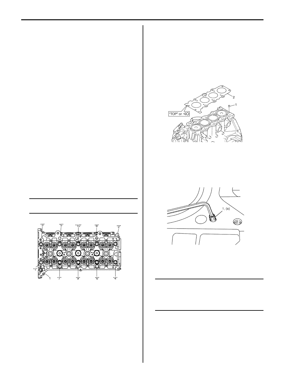
7) Loosen cylinder head bolts in such order as
indicated in the figure by using a 12 corner socket
wrenches and remove them.
NOTE
Don’t forget to remove bolt (M8) (1) as shown
in the figure.
8) Check all around cylinder head for any other parts
required to be removed or disconnected and remove
or disconnect whatever necessary.
9) Remove exhaust manifold referring to “Exhaust
Manifold Removal and Installation (For M16 Engine
Model) in Section 1K”, if necessary.
10) Remove cylinder head with intake manifold and
exhaust manifold. Use lifting device, if necessary.
Installation
1) Clean mating surface of cylinder head and cylinder
block. Remove oil, old gasket and dust from mating
surface.
2) Install knock pins (1) to cylinder block.
3) Install new cylinder head gasket (2) to cylinder block.
“Top” mark or “Triangle/circle” provided on gasket
comes to crankshaft pulley side, facing up (toward
cylinder head side).
4) Make sure that oil jet (venturi plug) (1) is not
clogged. If it is not installed, install it as specified
torque.
Tightening torque
Venturi plug (a): 5 N·m (0.5 kgf-m, 3.5 lb-ft)
5) Install cylinder head to cylinder block.
Apply engine oil to new cylinder head bolts and
tighten them gradually as follows.
NOTE
If cylinder head bolt (M10) is reused, make
sure to check cylinder head bolt (M10) for
deformation referring to “Cylinder Head Bolt”
under “Cylinder Head Inspection: For M16A
Engine with VVT”.
I2RH0B140088-01
I4RS0B140018-01
I2RH0B140089-01
Engine Mechanical: For M16A Engine with VVT 1D-35
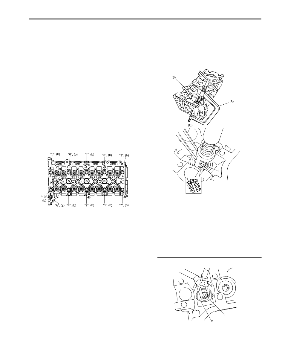
a) Tighten cylinder head bolts (“1” – “10”) to 20 N
⋅m
(2.0 kgf-m, 14.5 lb-ft) according to numerical
order as shown by using a 12 corner socket
wrenches.
b) In the same manner as in Step a), tighten them
to 40 N
⋅m (4.0 kgf-m, 29.0 lb-ft).
c) Turn all bolts 60
° according to numerical order in
the figure.
d) Repeat Step c).
e) Tighten bolt “A” to specified torque.
NOTE
Be sure to tighten M8 bolt “A” after securing
the other bolts.
Tightening torque
Cylinder head bolt for M8 (a): 25 N·m (2.5
kgf-m, 18.0 lb-ft)
Cylinder head bolt for M10 (b): 20 N
⋅m (2.0
kgf-m, 14.5 lb-ft), 40 N
⋅m (4.0 kgf-m, 29.0 lb-ft)
and then retighten by turning through to 60
°
twice
6) Install camshafts, tappet and shim referring to
“Camshaft, Tappet and Shim Removal and
Installation: For M16A Engine with VVT”.
7) Install timing chain referring to “Timing Chain and
Chain Tensioner Removal and Installation: For M16A
Engine with VVT”.
8) Install timing chain cover referring to “Timing Chain
Cover Removal and Installation: For M16A Engine
with VVT”.
9) Install cylinder head cover referring to “Cylinder
Head Cover Removal and Installation: For M16A
Engine with VVT”.
10) Install oil pan referring to “Oil Pan and Oil Pump
Strainer Removal and Installation: For M16A Engine
with VVT in Section 1E”.
Valves and Cylinder Head Disassembly and
Assembly
S5JB0A1416025
Disassembly
1) For ease in servicing cylinder head, remove intake
manifold, injectors, exhaust manifold from cylinder
head.
2) Using special tools (Valve lifter), compress valve
spring and then remove valve cotters (1) also by
using special tool (Forceps).
Special tool
(A): 09916–14510
(B): 09916–14521
(C): 09916–84511
3) Release special tools (Valve lifter), and remove
spring retainer and valve spring.
4) Remove valve from combustion chamber side.
5) Remove valve stem seal (1) from valve guide and
valve spring seat (2).
NOTE
Do not reuse valve stem seal once
disassembled. Be sure to use new seal when
assembling.
I2RH0B140091-01
I2RH0B140093-01
I2RH0B140094-01
Нет комментариевНе стесняйтесь поделиться с нами вашим ценным мнением.
Текст